
• Skip to main content
  • Skip to primary sidebar
  • Skip to footer
blog.draftsperson.net

blog.draftsperson.net

the art of technical drawing

blog.draftsperson.net

Metric Dimensioning Practices: Lines and Arrowheads

July 29, 2019

Last updated July 29, 2026

By Steve

Dimensioning practices for metric drawings are similar to those for non-metric drawings, but there are some subtle differences. This material outlines the current practices.

Dimension Lines and Projection Lines

Projection lines are used to indicate the extremities of a dimension. They are generally drawn up to 1 mm from the outline of the object. Dimension lines are used to label a particular dimension. They have one or more arrowheads, which are typically 3 mm long x 1 mm wide. Thin type B lines are used for both projection lines and dimension lines.
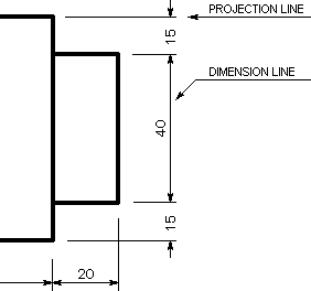
Dimensioned rectangle showing a projection line and a dimension line labelled, with vertical dimensions of 15, 40 and 15 and a horizontal dimension of 20

Linear Dimensions

Generally linear dimensions are in millimeters (millimetres). To avoid having to specify ‘mm’ after every dimension, a label such as ‘all dimensions in mm’ or ‘unless otherwise stated all dimensions are in mm’ is usually contained in the title block.

If the dimension is less than one a leading zero should be used before the decimal point. eg. 0.5 After reduction to microfilm and subsequent re-enlargement, the decimal point may sometimes become unreadable. To avoid possible misreading of the dimension a comma is often used instead of a decimal point. eg. 0,5 25,7

Angular Dimensions

Angular dimensions are usually specified in decimal degrees, degrees and minutes, or degrees minutes and seconds. eg. 27.5° 27°30′ 27°30’16” If the angle is less than one degree a leading zero should be used. eg. 0.5° 0°30′

Dimensioning Methods

Two methods of dimensioning are in common use. Unidirectional The dimensions are written horizontally.
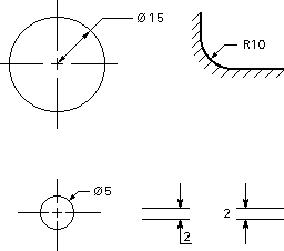
Unidirectional dimensioning: every value written horizontally regardless of the dimension line - a circle marked diameter 15, a fillet marked R10, a small circle marked diameter 5, and two thickness dimensions of 2

Aligned The dimensions are written parallel to their dimension line. Aligned dimensions should always be readable from the bottom or the right of the drawing.
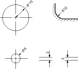
Aligned dimensioning: the same figures with each value written parallel to its own dimension line - diameter 15, R10, diameter 5 and two thickness dimensions of 2, all rotated to their leaders

Overall Dimensions

When several dimensions make up an overall length, the overall dimension can be shown outside these component dimensions. When specifying an overall dimension, one or more non-critical component dimensions must be omitted.
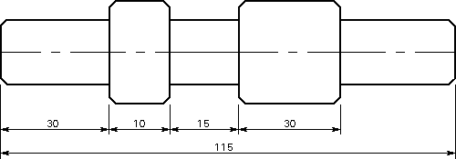
A stepped shaft dimensioned 30, 10, 15 and 30 along its length with an overall dimension of 115 below, one component dimension omitted so the chain is not over-dimensioned

Auxiliary Dimensions

When all of the component dimensions must be specified, an overall length may still be specified as an auxiliary dimension. Auxiliary dimensions are never toleranced, and are shown in brackets.
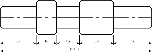
The same stepped shaft with every component dimension given - 30, 10, 15, 30, 30 - and the overall 115 shown in brackets as an auxiliary dimension, which is never toleranced

Dimensions not to Scale

Dimensions that are not to scale are underlined.

A dimension line with arrowheads at both ends reading 75.25, underlined to show the dimension is not to scale

Dimensions not Complete

When a dimension line cannot be completely drawn to its normal termination point, the free end is terminated in a double arrowhead.
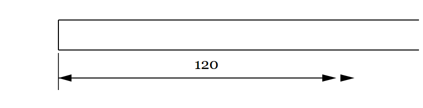
A dimension line reading 120 with a normal arrowhead at the projection line on the left, and a double arrowhead at the free end on the right where the dimension cannot be drawn to its true termination

Filed Under: Drafting Standards, Dimensions

Primary Sidebar

Subscribe to our Youtube Channel

Post CAD drafting jobs on Freelancer.com. and get some free money to do this.

Categories

  • American Steel Industry (4)
  • AutoCAD Articles & Reference (30)
  • AutoCAD Bugs & Problems (19)
  • AutoCAD Tips (29)
  • AutoCAD Tutorials (54)
  • AutoLISP Routines (328)
  • AutoLISP Tutorials (15)
  • CAD Standards (7)
  • Civil 3D (7)
  • Civil Drafting (4)
  • Dimensions (2)
  • Drafting Funnies (71)
  • Drafting History (9)
  • Drafting Standards (84)
  • Electrical Drafting (2)
  • General IT reference (7)
  • Geometry (15)
  • GIS (2)
  • Hatch Patterns (12)
  • Office Life Hacks (3)
  • PT (1)
  • Revit Tutorials (54)
  • Steel Detailing (14)
  • Structural Drafting (26)
  • Technical Dictionary (61)
  • Useful Website Links (19)

Footer

Free downloads

  • Free AutoLISP routines
  • Free hatch patterns
  • SHX fonts & text styles
  • Numbering LISP collection
  • ISO 3098B font

Reference charts

  • AWS weld symbols chart
  • Steel detailing chart
  • Hole & slot sizes
  • Bolt edge distance
  • ANSI & ARCH paper sizes
  • How to fold an A1 drawing

Useful links

  • CAD blocks (DWG)
  • Revit families
  • structuraldrafter.com
  • cad-corner.com
  • About
  • Privacy policy

Provided for free with no warranty · Log in