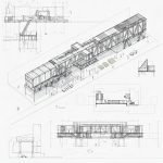
In the world of Computer-Aided Design (CAD), precision and clarity are paramount. A crucial element in achieving this is the consistent and correct use of units. For those working within the metric system (SI units), understanding which unit to employ for different types of drawings can streamline workflows, prevent errors, and ensure universal comprehension. This post will … [Read more...] about Decoding Metric: Choosing the Right Units for Your CAD Drawings
Drafting Standards
Top 5 Free DWG File Download Websites for CAD Drafting
Here are some of the best websites for free DWG file downloads for CAD drafting: blocks.draftsperson.net: This is one of the oldest and most comprehensive free CAD block websites around. It has a history dating back to 2002 and offers a wide range of categories, such as architecture, civil, equipment, furniture, people, vehicles, and more. You can download the DWG files … [Read more...] about Top 5 Free DWG File Download Websites for CAD Drafting
Drafting Standards – What metric units do I draw with?
What metric units do I use in my architectural, structural, building services or civil disciple drafting projects? Is it millimetres (mm), centimetres (cm), metres (m) or kilometres (km). In AutoCAD do I draw my architectural plan in mm or cm? How about Civil plans is it m or km? What is the industry drafting standard? In this video tutorial I will show you what is used on a … [Read more...] about Drafting Standards – What metric units do I draw with?
What symbols to use for valves
For my P&ID drafting of valves, what industry standard symbols should I use? A handy chart for P&ID Drafting DWG and PDF file formats of these symbols can be downloaded at: https://blocks.draftsperson.net/download/pid-valve-symbols/ … [Read more...] about What symbols to use for valves
Holes and Slots, Standard Sizes
This information applies to the American Steel Industry. Holes and Slots Standard Holes Standard hole sizes for bolts are made 1/16-in. larger in diameter than the nominal size of the fastener body. This provides a certain amount of play in the holes, which compensates for small misalignment's in hole location or assembly, and aids in the shop and field entry of … [Read more...] about Holes and Slots, Standard Sizes
Welding Symbols Chart – AWS
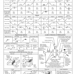
Eerrata for AWS (American Welding Society) A2.4-98, Standard Symbols for Welding, Brazing, and Nondestructive Examination.This is the correction to the Welding Symbol Chart for AWS A2.4-98, pages 106 and 107. AWS A2.4-98 Standards Symbols for Welding Bracing and Nondestructive Examination Page 106 AWS A2.4-98 Standards Symbols for Welding Bracing and Nondestructive … [Read more...] about Welding Symbols Chart – AWS


