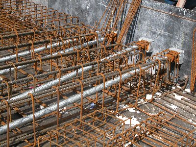
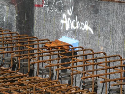
The drafters drafting survival guide to pre-stressed/post-tensioned concrete slabs.
By Allan Wise
Please note: This information has been compiled by drafters working in the Australian PT concrete slab industry. This information may apply to other countries/systems.
Disclaimer this is information is for a guide only. While this article was complied by drafters actively involved in PT drafting, errors or mis-understandings may occur.
Sample of an Engineering PT slab drawing
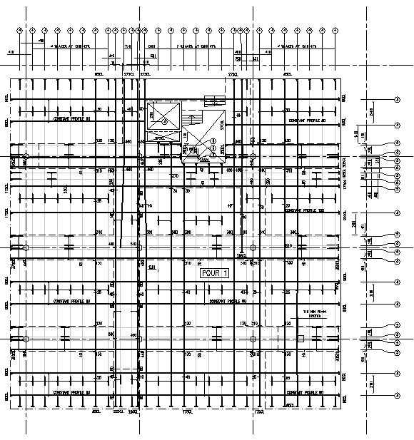
Download this sample AutoCAD 2000 format 68kb
Definitions
PT: A method of pre-stressing reinforced concrete with tendons tensioned when the concrete reaches a specific strength. Mono-strand live end.
TENDON: An bundle of strands.
STRANDS: A single wire in a tendon. Think of the chords that make the rope.
DUCT: The tube in which the tendons fit.
ANCHORAGE The end dangle bits on the duct that ‘anchor’ it all into the concrete. Commonly at one end is the live end anchor and the other the dead end anchor.
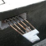
Mono-strand live end 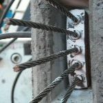
Mono-strand stressed live end 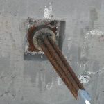
Multi-strand live end 
Plastic pan form 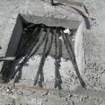
Pan live end
What do the Symbols Mean?
 | Live End – At this anchorage the hydraulic jack attaches to the strands and “stresses” them |
 | Dead End – An anchorage cast into the concrete |
 | Number of Strands, in the circle. And the size of strand, commonly Dia 12.7 or 15.2. Often a cover note can be used: “ALL STRANDS DIA 12.7 U.N.O.” |
 | Live End with Pan – Used for surface stressing when an anchorage cannot be placed on a vertical concrete face. |
 | Overhead/soffit postion live end. Stressed from the underside of the slab. |
 | Stressing Coupler |
The Two Main Systems of Stressing
1. Mono-Strand System – Strand stressed individually, usually an oval shaped duct with rectangular shaped anchorages. The most common system used for stressing slabs.
2. Multi-Strand System – All strands stressed simultaneously, usually a round duct with square shaped anchorages.
Engineering PT drawings: What to Draw
These are the engineering design drawings produced for costing etc. pre shop drawings stage.
- All anchorage locations (live ends, dead ends, couplers etc.)
- Size of the strands in the duct
- Number of strands in the duct
- High and low points of duct. Dimension is taken from slab soffit to underside of duct. Same PT duct runs can be linked together.
Shop PT drawings: What to Draw
These are the drawings used on site
- All anchorage locations (live ends, dead ends, couplers etc.)
- All PT duct runs
- Size of the strands in each duct
- Number of strands in each duct
- Unique identifying number (per pour) for each PT run
- Dimensions from grids or walls/columns under to all anchorage points
- Dimensions to variations in the duct run. I.e. the duct does not go in a straight line from live end to dead end which are dimensioned.
- Soffit of concrete to underside of duct dimensions at 1 metre spacings
Drafting Rules of Thumb
- Avoid placing text over the thick lines.
- Generally anything greater than 6 Dia 12.7 of 5 Dia 15.2 use the multi-strand system. Anything less use the mono-strand system.
- Double live ends can be used on longer PT runs
- In band beams > 30m run approx.
- In slabs > 40m run approx.
- In distribution or slabs of ground > 50m run approx.
- Minimum set out dimensions
- Between live ends: 300mm min horizontal. 100mm min vertical
- Between Dia 12.7 mono-strand tendons: 150mm min horizontal, 100mm min vertical.
- Between Dia 15.2 mono-strand tendons: 175mm min horizontal and 125mm min vertical
- Concrete Cover: PT at low points to be chaired at a minimum cover of 25mm to avoid concrete popping out. At high points 20mm cover for the same reason.
- Reinforcing bars clashing with tendons should be re-layered in a different order or noted on plan to be installed after the PT tendon has been installed.
- High points over supports, low points mid-span.
Photos of PT components
