
Last updated July 29, 2026
Applies To:
- Work with Revit Structure 2008. May apply to other versions
Problem:
How to add a rotation parameter to a component family with fixed geometry. Suppose you would like to add a rotation parameter to some 2D or 3D geometry (component family) that otherwise does not have any parameter attached to it. This would most likely happen for any imported geometry (DWG) or any basic building block, created directly in the Revit family editor.
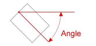
We’ll use the example of a basic solid extruded rectangle, created inside of Revit. It has to be able to rotate about its insertion point (middle left of the object, indicated by the point in the next image).
Solution:
First of all, create the Family using the ‘Metric Generic Model’ template.
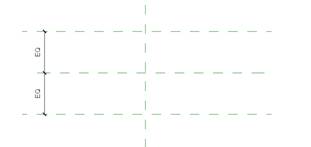
Inside of the family, create two horizontal reference planes about the Center(Front/Back) reference plane and constrain them to ‘equal distance’ (this is to make sure that the insertion point will be in the middle of the object, otherwise they don’t have any use).
Now create the solid extruded rectangle, its top left at the intersection of the vertical ref plane with the top most horizontal ref plane and its bottom right somewhere along the bottom horizontal ref plane to the right of the vertical ref plane.
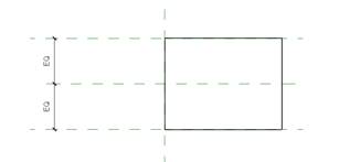
Make sure you have finished sketch mode. Now draw a reference line from the origin intersection to the right at 0 degrees.
|
|
|||
|
|||
Rotation parameter to a component family with fixed geometryApplies To:
Problem:How to add a rotation parameter to a component family with fixed geometry. Suppose you would like to add a rotation parameter to some 2D or 3D geometry (component family) that otherwise does not have any parameter attached to it. This would most likely happen for any imported geometry (DWG) or any basic building block, created directly in the Revit family editor.
We’ll use the example of a basic solid extruded rectangle, created inside of Revit. It has to be able to rotate about its insertion point (middle left of the object, indicated by the point in the next image).
 Solution:First of all, create the Family using the ‘Metric Generic Model’ template.
Inside of the family, create two horizontal reference planes about the Center(Front/Back) reference plane and constrain them to ‘equal distance’ (this is to make sure that the insertion point will be in the middle of the object, otherwise they don’t have any use).
 Now create the solid extruded rectangle, its top left at the intersection of the vertical ref plane with the top most horizontal ref plane and its bottom right somewhere along the bottom horizontal ref plane to the right of the vertical ref plane.
 Make sure you have finished sketch mode. Now draw a reference line from the origin intersection to the right at 0 degrees.
 Create another component family based upon the ‘Metric Generic Model’ template and load the newly created solid rectangle. Then insert an instance at the origin and rotate it about the same origin. Assign an angular parameter to this rotation (instance or type).
|
|||

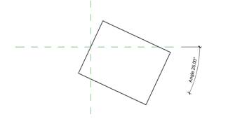
The family is ready. Load it into a project and insert some instances. Depending on the parameter being an instance or type parameter, all instances or just the selected ones will rotate when changing the angle parameter, defined in their properties.