
Last updated July 27, 2026
A welding symbol tells the fabricator exactly what weld to make, where to make it, how big, and how to finish it — in a mark small enough to fit beside a detail. This guide covers the American system, AWS A2.4, which is what most steel detailing offices work to. Every weld type and supplementary symbol is set out below in plain text so you can search this page, plus the printable chart at the bottom for pinning above the desk.
Standards note, July 2026. The current AWS edition is AWS A2.4:2020, the 8th edition, ANSI-approved on 9 January 2020. Many charts circulating online — including older copies on this site — still show A2.4-98, which is three revisions behind. Australian readers should also know that AS 1101.3:2026 was published on 26 June 2026, superseding AS 1101.3-2005. We will cover the Australian standard separately once we have worked through the new edition properly; everything below is the AWS system.
The anatomy of a welding symbol
Only two parts are compulsory. AWS A2.4-98 clause 1.3 puts it plainly: “Only the reference line and arrow are required elements.” Everything else is added as the joint demands.
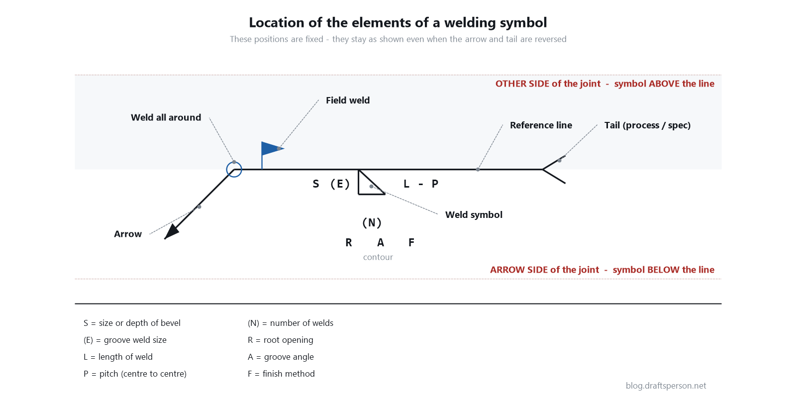
- Reference line — the horizontal backbone. Always drawn horizontal, always read left to right. Every other element is positioned relative to it.
- Arrow — connects the reference line to the joint. It must point to a line that conclusively identifies the joint, preferably a solid object line, though a hidden line is permitted.
- Weld symbol — the graphic showing the type of weld, drawn on the reference line.
- Dimensions — size, length, pitch, root opening and groove angle, each in its own fixed position.
- Supplementary symbols — weld-all-around, field weld, melt-through, contour and finish.
- Tail — an open V at the far end, carrying the process, specification or any note that will not fit elsewhere. Omitted when there is nothing to say.
Worth getting the terminology right, because most sources muddle it: the weld symbol is the little graphic for the weld type. The welding symbol is the whole assembly — reference line, arrow, weld symbol, dimensions, supplementary symbols and tail together.
Arrow side and other side — the rule that matters most
Get this wrong and the weld ends up on the wrong face of the joint. There are two separate parts to it.
Which side is which. The arrow side is the side of the joint the arrow points to. The other side is the opposite side. For fillet, groove and flange welds the arrow points at one side of the joint, and that becomes the arrow side. For plug, slot, spot, seam, projection and stud welds the arrow points to the outer surface of one member at the centreline of the weld, and that member is the arrow-side member.
Where the symbol goes. A weld symbol drawn below the reference line means the weld is on the arrow side. Drawn above the line, it means the other side. Symbols on both sides mean weld both sides. A few symbols — spot, seam, and square groove among them — may straddle the line, meaning the side has no significance.
Why not simply say “near side” and “far side”? Because those terms fall apart in section. The A2.4-98 foreword explains that near side and far side caused confusion “because when joints are shown in section, all welds are equally distant from the reader.” The arrow decides, not the viewpoint.
One more trap: the dimension positions are absolute. Size sits to the left of the weld symbol and length-pitch to the right even if the arrow and tail are swapped end for end. The layout does not mirror.
Weld type symbols
Unless noted otherwise, each symbol goes below the reference line for an arrow-side weld, above it for the other side, and on both sides for a double weld.
Fillet and groove welds
| Weld | How the symbol is drawn | What it means |
|---|---|---|
| Fillet | A right-angled triangle on the reference line. The perpendicular leg is always on the left, whichever way the arrow points. | Roughly triangular weld joining two surfaces at about right angles — lap, T and corner joints. No edge preparation. Size is the leg length, written to the left. |
| Square groove | Two short parallel lines perpendicular to the reference line, open at the ends. | Butt joint with no edge preparation; members left square-cut. Any root gap is dimensioned between the lines. Used on thin material. |
| V-groove | A V sitting on the reference line, opening away from it. Both sides gives an X. | Butt joint with both members bevelled. Groove angle is written outside the V, root opening inside. |
| Bevel groove | A half-V: one perpendicular line plus one angled line, perpendicular leg on the left. | Only one member is bevelled, the other left square. The arrow is normally broken to point at the member to be prepared. |
| U-groove | A U on the reference line, opening away from it. | Both members prepared with a radiused concave groove face, leaving a root face. Needs less weld metal than a V on thick material. |
| J-groove | A J shape, square side on the left. | One member radiused, the other square. J is to U what bevel is to V. |
| Flare-V groove | Two arcs back to back, curving away from each other. | The groove is formed by the natural radii of two curved members — two round bars, or two formed tube corners meeting. |
| Flare-bevel groove | One arc plus one perpendicular line. | The groove is formed by the radius of one curved member against a flat one — round bar or the rounded corner of RHS/CHS onto plate. Very common in tube work. |
Plug, slot and resistance welds
| Weld | How the symbol is drawn | What it means |
|---|---|---|
| Plug | A rectangle on the reference line. Never used for “both sides”. | A weld made in a circular hole through one member of a lap or T joint, fusing it to the other. Hole diameter goes to the left. |
| Slot | The same rectangle as the plug weld. | The elongated-hole version. Distinguished from a plug weld by its dimensioning, not a different symbol: the value to the left is the slot width. |
| Spot | A plain circle. Straddling the line means no side significance. | A weld between faying surfaces producing a roughly circular nugget, no joint preparation. |
| Seam | A circle with two parallel lines drawn through it, extending past on both sides. | A continuous or intermittent weld between faying surfaces — effectively an elongated spot weld. Size to the left is the weld width. |
| Projection | The same circle as the spot weld; the process reference goes in the tail. | A resistance weld made at preformed projections on one member. |
Back, surfacing, edge and stud welds
| Weld | How the symbol is drawn | What it means |
|---|---|---|
| Back or backing | A single semicircle, flat side on the reference line, placed opposite the groove weld symbol. | Back weld: deposited on the root side after the groove weld, usually following backgouging, to guarantee sound penetration. Backing weld: deposited before the groove weld. Same symbol, sequence tells them apart. |
| Surfacing | Two adjacent semicircular arcs, drawn below the line only. | Weld metal deposited on a surface rather than in a joint — build-up, hardfacing, restoring a worn dimension. No joint, so arrow-side only. |
| Edge | Two parallel perpendicular lines closed off at the far end. | A weld on the edges of two or more approximately parallel members. Mostly sheet and light-gauge work. |
| Stud | A circle with an X through it, drawn below the line only. | A stud attached by stud arc welding. It can only go on the surface the arrow points at, so it has arrow-side significance only. |
| Scarf (brazing) | Two short slanted parallel lines across the reference line. | A scarfed joint preparation for brazing. AWS A2.4 covers brazing with the same conventions. |
Supplementary symbols
| Symbol | Drawn as | Meaning |
|---|---|---|
| Weld all around | An open circle at the kink where the arrow meets the reference line. | The weld continues completely around the joint. |
| Field weld | A solid triangular flag on a short staff, at the same kink. | The weld is made on site, not in the shop. |
| Melt-through | A solid filled semicircle opposite the weld symbol. | Complete joint penetration from a weld made from one side, with visible root reinforcement. |
| Backing | An open rectangle opposite the groove weld symbol. | A backing bar or strip is required. If it must be removed afterwards, that is noted. |
| Consumable insert | An open square opposite the groove weld symbol. | A preplaced insert that becomes part of the finished weld. |
| Spacer | A rectangle drawn through the reference line, interrupting it. | A spacer sits in the root between two prepared members of a double groove weld. |
| Flush contour | A straight line just outside the weld symbol. | The weld face is finished level with the adjacent base metal. |
| Convex contour | An arc bulging away from the reference line. | The weld face is crowned. |
| Concave contour | An arc dished toward the reference line. | The weld face is hollowed. |
Finish letters sit immediately outside the contour symbol and specify the method of finishing, not the degree of finish. In the AWS system: C chipping, G grinding, H hammering, M machining, R rolling, U unspecified.
Where the dimensions go
- Left of the weld symbol — size, or depth of bevel. Where a groove weld has both a bevel depth and a weld size, the size follows in brackets.
- Right of the weld symbol — length, then pitch, written
L-P. Pitch is centre-to-centre spacing of intermittent weld segments. - Stacked outward on the symbol side — root opening, then groove angle, then the contour symbol, with the finish letter outermost.
- In brackets — the number of spot, seam, stud, plug, slot or projection welds.
Reading a symbol: two worked examples
A 6 mm fillet, both sides, welded all around on site. Triangles above and below the reference line, 6 to the left of each, an open circle at the kink and a flag beside it. Read it as: fillet weld both sides of the joint, 6 mm leg, continuous right around the section, made on site.
An intermittent fillet, arrow side only. One triangle below the line, 8 to the left, and 50-150 to the right. That is an 8 mm fillet on the arrow side, in 50 mm runs spaced 150 mm centre to centre — so 100 mm of gap between each run, not 150.
That last distinction catches people out regularly: pitch is measured centre to centre, not gap to gap.
What changed in AWS A2.4:2020
If you are working from an older chart, these are the changes worth knowing, taken from the 2020 foreword:
- Detailed usage was added for flare groove welds.
- The diameter symbol is no longer part of the plug weld symbol itself, though it is still required when designating the plug dimension.
- A contour symbol without a designated finishing method no longer means the contour must be achieved by welding alone — any method is now acceptable.
- The flat contour symbol is now limited to fillet welds; flush is used for groove, plug and slot welds.
- A combination groove weld symbol may be drawn backward to reflect the actual joint configuration.
- For spot and seam welds, the dimension to the left now designates size only, with strength noted in the tail.
- Flash and upset welding symbols are no longer supported — use a reference line and arrow with FW or UW in the tail.
The standard has a long lineage: AWS A2.0 first appeared in 1947, was combined with A2.2 to create A2.4 in 1976, and has been revised as A2.4-76, -79, -86, -93, -98, then A2.4:2007, A2.4:2012 and A2.4:2020.
The printable AWS chart
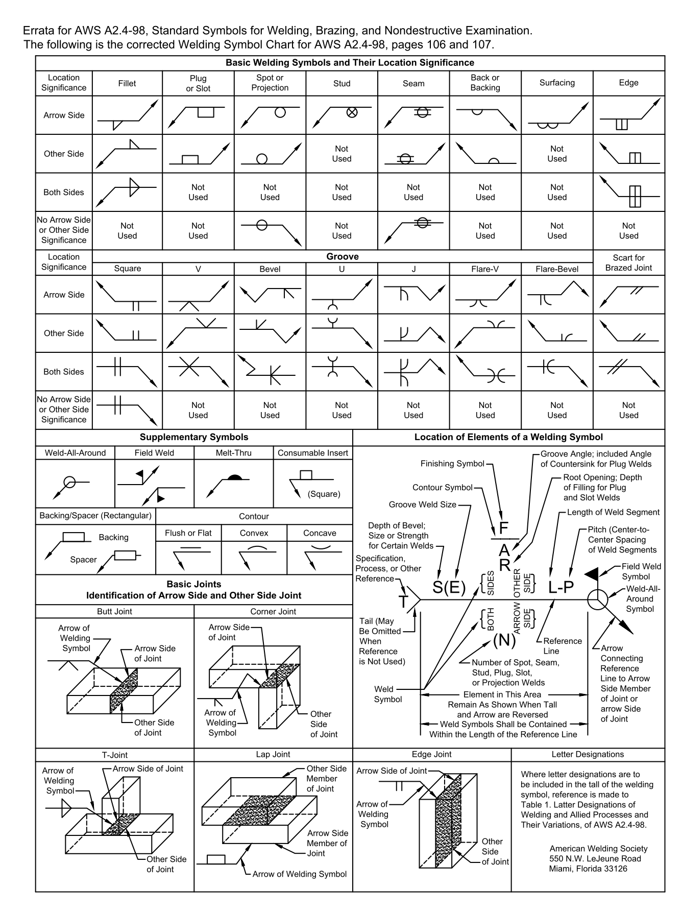
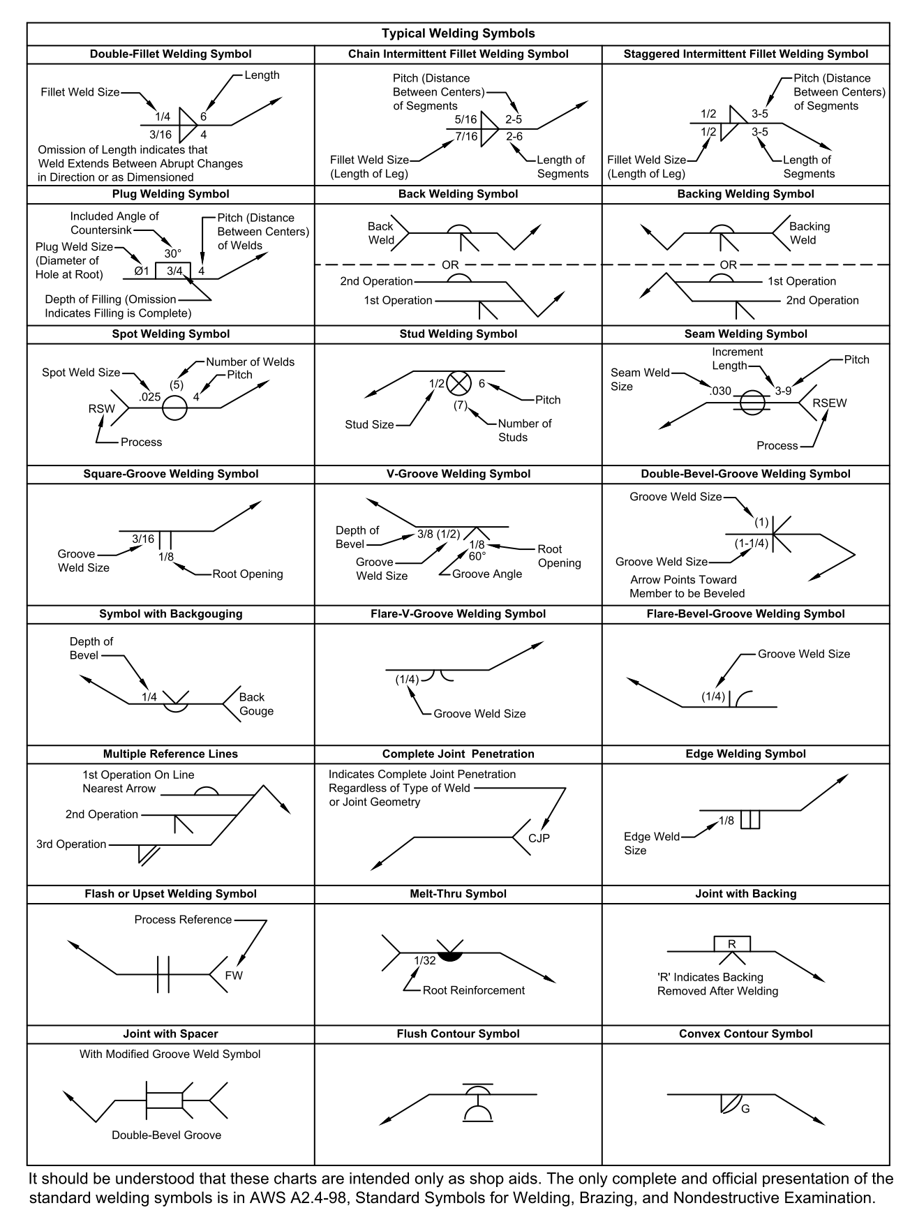
These two pages are the errata for AWS A2.4-98 — the corrections to the welding symbol chart on pages 106 and 107. They remain a useful one-page overview: the basic weld symbols and their location significance, the supplementary symbols, the location-of-elements drawing, isometric views identifying arrow side and other side, and worked examples. Note the edition: these are 1998 pages, so read them alongside the 2020 changes listed above.
Downloads
More steel detailing references
- Standard hole & slot sizes for bolts
- Minimum bolt edge distances
- Calculating structural bolt lengths
- Printable steel detailing chart
References
- AWS A2.4:2020, Standard Symbols for Welding, Brazing, and Nondestructive Examination — the current edition; edition history and the list of 2020 changes are taken from its foreword
- AWS A2.4:2020 free preview (PDF) — title page, foreword and table of contents
- The National Board of Boiler and Pressure Vessel Inspectors — welding symbols — arrow-side convention and fillet symbol orientation
- Open Oregon, Interpretation of Metal Fab Drawings — open textbook used to cross-check symbol meanings
- Standards Australia — AS 1101.3:2026 — publication date and superseded editions