
Last updated July 27, 2026
Weld symbols on Australian drawings are governed by AS 1101.3 — Australia has its own welding symbol standard rather than adopting the international one. In practice it reads much like the American system, with one important set of differences that catch people out when a drawing arrives from overseas.
This page covers the Australian convention and what changes when the drawing comes from America or Europe. For the full symbol-by-symbol reference, see our AWS weld symbols chart and guide, or the illustrated American weld symbols page.
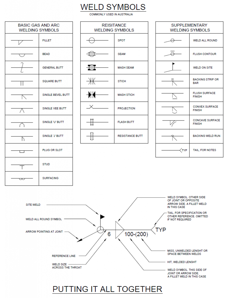
Download the AutoCAD DWG file of the weld symbols chart above — free, ready to drop into your drawing.
The Australian standard
The current document is AS 1101.3-2005, Graphical symbols for general engineering — Part 3: Welding and non-destructive examination, published by Standards Australia and reconfirmed in 2018 (which is why you will see it written as AS 1101.3-2005 (R2018)). It superseded the 1979 edition.
Two things follow from that, and both matter.
First, Australia is not on ISO 2553. Plenty of people assume that because Australia adopts ISO standards so widely elsewhere. Weld symbols are their own document here.
Second, the standard dates from 2005 and was reconfirmed rather than revised in 2018. ISO 2553 has been through two editions since — 2013 and 2019 — so the gap between the Australian document and the international one has been widening, not closing.
Why it reads like an American drawing
Because it is one. The preface to AS 1101.3 says so directly:
The 1987 edition of the Standard was generally based on ANSI/AWS A2.4-79, Symbols for Welding and Non-destructive Testing, and the permission of the American Welding Society Inc. to use their Standard was acknowledged. This edition continues to follow the ANSI/AWS A2.4, and takes cognizance of its 1998 edition.
So the Australian standard is an AWS document with Australian names on the welds. That single sentence explains most of what a detailer notices when they compare the two.
The committee looked at the ISO system and said no
This is the part worth knowing, because it means Australia’s position is a decision rather than an accident. Also from the preface:
The committee noted the practice currently adopted in ISO 2553, Welded, brazed and soldered joints; symbolic representation on drawings, in regard to the position of the symbols on drawings, viz., the dual reference line, and felt that this situation should not be carried over into this Standard. Therefore, the practice of using one continuous reference line remains unaltered in this edition.
They considered the dashed second line, and declined it. Clause 2.1.1 confirms it in the body of the standard, listing the first element of a welding symbol as “Reference line (shown horizontally)” — singular.
The architecture, clause by clause
The publisher’s preview of the standard shows all of the following:
- Arrow side and other side significance. Clause 5.2.2 is headed “Arrow side significance”. That framing — which side of the reference line a symbol sits on determines which side of the joint gets welded — is the American model, not the ISO one.
- Size to the left, length to the right. Weld size goes to the left of the symbol, length to the right. Clause 6.6 places length “to the right of the weld symbol”; Clause 5.3.1 puts the built-up thickness “to the left of the weld symbol”.
- Intermittent welds as length–pitch. Clause 6.7.2: “The pitch of intermittent edge welds shall be specified to the right of the length dimension following a hyphen.” So 50-150 means 50 long at 150 centres. Chain intermittent welds sit opposite each other across the joint (6.7.3); staggered ones are offset (6.7.4).
- Multiple reference lines for sequenced operations. Clause 4.8: a second reference line may be used “for a second operation, which cannot be performed until after the first is completed” — back gouging then welding being the classic case.
- Backing and spacer conventions built the same way as the American ones: the butt weld symbol on one side of the reference line and a rectangle on the other (Clause 4.6).
If you have learned weld symbols from American material, none of that will surprise you. Which is the point: for the day-to-day symbols, an Australian drawing and an American drawing read the same way.
But the words are different
Where the two part company is vocabulary. AS 1101.3 says butt weld where AWS A2.4 says groove weld — Clauses 4.6, 4.7 and 5.5 all refer to “the butt weld symbol”. It also uses backing run alongside backing weld.
The naming follows British and international usage even though the symbol framework follows the American one. It is a mixed inheritance, and it is worth knowing when you are searching for guidance: an Australian detailer looking up “groove weld” will find American material that is structurally correct for their drawing, under a name their own standard does not use.
The mixture is not perfectly tidy, either — Clause 6.3 still says “flare-bevel or flare-V groove weld”. Both words survive in the one document.
The gap that has opened up
AS 1101.3 follows AWS A2.4 as it stood in 1998. AWS has published three editions since — 2007, 2012, and the current AWS A2.4:2020, its 8th edition, ANSI-approved in January 2020.
So the two systems have been quietly drifting apart for a quarter of a century. Some of the 2020 changes are concrete enough to catch you out on a current American drawing — for instance, AWS changed how spot and seam welds are dimensioned:
The dimension to the left of the weld symbol will only designate the size of the weld. If strength is needed, this information will be required to be specified as a note.
Our AWS weld symbols guide covers what changed in A2.4:2020 in more detail.
The Australian bit AWS does not have
On structural steelwork drawings here, the weld category from AS/NZS 1554.1 — SP (structural purpose) or GP (general purpose) — is written in the tail of the welding symbol, the position AS 1101.3 Clause 2.1.5 reserves for “specification and process references”.
There is no AWS equivalent of that convention. If you are reading an Australian structural drawing, the tail is where the weld quality requirement lives, and it is not optional information.
Two more Australian details from the same territory:
- Incomplete penetration butt welds are called up by throat, not size. The Welding Technology Institute of Australia’s commentary on AS/NZS 1554 puts it plainly: “In lieu of specifying the size of an incomplete penetration butt weld, the drawings should show the required design throat thickness.” So on the one drawing, a fillet is dimensioned by leg and an incomplete-penetration butt weld by throat.
- Backing notations are M and MR. AS 1101.3 Clause 4.6 defines M as “material as specified” and MR as “same as M but removed after welding”, written inside the rectangle on the far side of the reference line.
When the drawing comes from Europe
This is where it stops being a vocabulary problem and starts being a fabrication problem.
The international standard is ISO 2553:2019, Welding and allied processes — Symbolic representation on drawings — Welded joints, now in its fifth edition. It does something no other weld symbol standard does: it defines two systems and lets the drawing choose.
From the standard’s own scope:
It is recognized that there are two different approaches in the global market to designate the arrow side and other side on drawings.
- System A uses a dual reference line — a continuous line with a dashed line alongside it. Which line your symbol sits on tells you which side of the joint it applies to. This is the European convention, based on the 1992 edition of ISO 2553.
- System B uses a single reference line, with above and below the line carrying the meaning. ISO describes this one as being based on standards used by Pacific Rim countries — and it is the arrangement an Australian or American detailer already knows.
And a rule worth committing to memory, quoted from Clause 4.3:
System A and B shall not be mixed and drawings shall clearly indicate which system is used.
So if you receive an ISO drawing, the first thing to look for is the note saying which system it is drawn to. If there is a dashed line running alongside the reference line, you are in System A and the dashed line is doing work — it is not a drafting flourish.
And here is the trap. On an Australian or American drawing the rule is positional: a symbol below the reference line is the arrow side, above is the other side. Under ISO System A the rule is not positional — it is which line the symbol sits on. The continuous line is the arrow side and the dashed line is the far side, and the dashed line may be drawn either above or below the continuous one.
Which means the habit you have built up over years — glance at whether the triangle is above or below the line — will give you the wrong answer roughly half the time on a System A drawing. Look for the dashed line first, then read the symbol.
The two differences that will actually bite you
1. Fillet weld sizes carry a letter under ISO
On an Australian or American drawing, a fillet size is written bare to the left of the symbol and it is the leg length.
ISO 2553:2019 defines three prefix letters, and the letter tells you what is being dimensioned:
| Prefix | ISO 2553:2019 term | What it measures |
|---|---|---|
| a | nominal throat thickness | Height of the largest isosceles triangle that fits inside the weld section |
| z | leg length | Across the fusion face — the same thing the AS/AWS bare number means |
| s | deep penetration throat thickness | Throat thickness plus a specified amount of penetration |
So z8 is an 8 mm leg, and a6 is a 6 mm throat — which is a noticeably bigger weld. Read a6 as if it were an Australian bare-number leg size and you will under-weld the joint.
This is not a theoretical concern. The Welding Technology Institute of Australia flags it explicitly in its commentary on AS/NZS 1554:
Australian and New Zealand practice is to denote the size of fillet welds by the leg length while European practice is to use the throat dimension. Users should be wary of this when using European drawings and specifications.
The Americans treat it as a known trap too — AWS A2.4:2020 carries an informative annex comparing ISO and AWS symbols, with a figure dedicated to the fillet weld “a” or “z” modifier.
2. Butt welds default to full penetration under ISO
This one is the more consequential of the two, because nothing on the drawing announces it. ISO 2553:2019 states, in a footnote to its table of elementary symbols:
Butt welds are full penetration unless otherwise indicated by dimensions on the welding symbol or by reference to other information, for example the WPS.
The AS and AWS systems work the other way round: complete penetration is called up, with AS 1101.3 referring at Clause 6.4 to “the complete penetration symbol” placed on the opposite side of the reference line.
Same plain butt weld symbol, opposite default. On an ISO drawing it means full penetration; on an Australian one it does not. That is not a detailing preference — it changes the weld.
Quick comparison
| AS 1101.3 (Australia) | AWS A2.4 (USA) | ISO 2553 (international) | |
|---|---|---|---|
| Reference line | Single | Single | Dual (System A) or single (System B) |
| Name for the weld | Butt weld | Groove weld | Butt weld |
| Fillet size | Bare number = leg | Bare number = leg | z = leg, a = throat, s = deep penetration |
| Butt weld penetration | Called up explicitly | Called up explicitly | Full penetration by default |
| Size and length | Size left, length right | Size left, length right | Size left, length right |
The short version
- Australian drawings work to AS 1101.3-2005 (R2018) — our own standard, not ISO 2553.
- Its structure follows the American model: arrow side and other side, size left, length right, length–pitch intermittent welds.
- Its vocabulary follows British and international usage: butt weld, not groove weld.
- On an ISO drawing, check which system it is drawn to. A dashed reference line means System A.
- On an ISO drawing, a fillet size with an a is a throat, not a leg.
- On an ISO drawing, a plain butt weld symbol means full penetration unless told otherwise.
Related on this site: the full AWS weld symbols chart and guide with a free printable chart, the illustrated American weld symbols page, and basic welding symbols explained with worked examples.
References
- AS 1101.3-2005 (R2018) — Graphical symbols for general engineering, Part 3: Welding and non-destructive examination — Standards Australia, listed via Building CodeHub. Designation, title, 2005 publication and 2018 reconfirmation, and scope.
- AS 1101.3-2005 (R2018) — publisher preview, front matter — the preface quotes above: the derivation from ANSI/AWS A2.4-79 and continuation from its 1998 edition, and the committee’s stated decision not to adopt the ISO 2553 dual reference line. Also the eight elements of a welding symbol (Clause 2.1.1) and specification references in the tail (Clause 2.1.5). Third edition; originated as AS Z6-1955; previous edition 1987.
- AS 1101.3-2005 (R2018) — publisher preview, pages 56–66 — arrow side significance (5.2.2), size and length placement (5.3.1, 6.6), intermittent weld pitch (6.7.2–6.7.4), multiple reference lines (4.8), backing and spacer (4.6, 4.7), complete penetration (6.4), and the “butt weld” naming.
- AWS A2.4:2020 — Standard Symbols for Welding, Brazing, and Nondestructive Examination, preview — American Welding Society, 8th edition, ANSI-approved 9 January 2020. The spot and seam dimensioning change, and Annex F comparing ISO and AWS symbols including the fillet “a” or “z” modifier.
- Technical Note 11: Commentary on the Standard AS/NZS 1554 Structural Steel Welding — Welding Technology Institute of Australia. The leg-length versus throat warning for European drawings, design throat thickness for incomplete penetration butt welds, and the M / MR backing notations.
- ISO 2553:2019 — Welding and allied processes: Symbolic representation on drawings, Welded joints — ISO Online Browsing Platform (free to read). Fifth edition, March 2019.
- ISO 2553:2019 — official preview — the System A / System B definitions and the “shall not be mixed” rule (Clause 4.3); the a, z and s definitions (Clause 3.16, 3.17, 3.19); and the full-penetration default (Table 1, footnote b).
- AS 1101.3-2005 (R2018) — Standards Australia store, to purchase the full text.
- Standard Drawing Symbols Abbreviations Graphical Representation — OTEN, revised edition 1981.
- Engineering Drawing Handbook — Standards Australia, 1993.