
Last updated July 28, 2026
Cutter Soil Mix — CSM — is a way of building a retaining or cut-off wall out of the ground that is already there. A cutter head chews through the soil in place while cement grout is injected and mixed in. What sets is a wall of treated soil, not a wall of imported concrete.
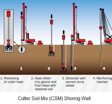
How it works
Binding agent, generally cement, is injected with water and air and mixed into the in-situ soil. Once cured, the mixed soil will retain soil and water for deep excavations, act as an environmental cut-off, or carry structural load from roads, embankments, tanks and other movement-sensitive structures.
The technique differs from older soil mixing in the tool. Instead of an auger turning about a vertical axis, CSM uses cutter wheels on a drive head that rotate about the horizontal axis, like a diaphragm walling mill. With full computer instrumentation and built-in inclinometers, that lets CSM panels be built to accurate vertical tolerances — which is the property that makes them useful as a retention wall rather than just ground improvement.
It suits granular soils best, but will also go through clays and some lower-quality rock.
The geometry you will be drawing
- Panel thickness — 550 mm or 1000 mm.
- Panel length — typically 2,200 mm.
- Reinforcement — UC or UB sections lowered into the freshly cast panel, at spacings to suit the structural loads.
Note what that means for a plan: this is a wall made of rectangles, not circles. Panels are set out end to end with an overlap, primary and secondary, and the setout drawing is a run of rectangles rather than the string of overlapping circles you draw for a secant pile wall. It is a different-looking drawing for a different-looking machine.
The steel is not in every panel. Sections go in where the structural design needs them, so the reinforcement layout is its own drawing rather than something you can infer from the panel setout.
Why it gets chosen over secant piles
Two reasons, and both are worth understanding because they explain the details you will be asked to draw.
Less wasted section. A rectangular panel is a more efficient structural section than a row of overlapping circles, where a good deal of each circle is doing nothing. Less cross-sectional area means less material and less spoil.
Far fewer joints. A secant wall has a joint at every pile overlap. A CSM wall of 2,200 mm panels has a joint roughly every 2 metres instead of every 600 or 900. Every joint is a place water can find its way through a cold joint, so fewer joints means a wall that leaks less — which matters a great deal if the wall is there to keep groundwater out of a basement.
As a foundation rather than a wall
CSM is also used under movement-sensitive structures — roads, tanks, embankments — where it is behaving as a barrette rather than a retaining wall.
The reason it works there is geometric. A barrette 550 or 1,000 mm wide by around 2,400 mm long has a large surface area for its volume, so it develops significant shaft friction; and it has a large cross-sectional area at the head, with a material stiffness lower than concrete. The combination spreads load into the structure above instead of punching through it.
What to put on the drawing
- Panel setout in plan, numbered, with primary and secondary panels distinguished and the overlap dimensioned.
- Top and toe levels for each panel, to AHD, not relative depths — the rig works to levels.
- Reinforcement sections: size, length, top and bottom levels, and which panels get one.
- A typical section showing the wall against the excavation, with any capping beam, anchors or props.
- The specified mix strength, which comes from the geotechnical design, not from you.
Ground conditions govern all of this. CSM is a geotechnical design decision and the dimensions above are what the technique can do, not what your project should have.
References
- Vibropile — the source of the technical description above
- Structural slab joints
- AHD on a drawing — the datum panel levels are set to
- Acronyms and abbreviations in engineering