
Last updated July 28, 2026
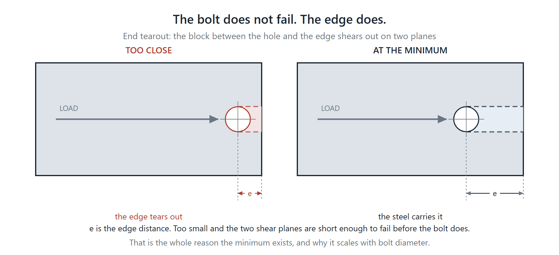
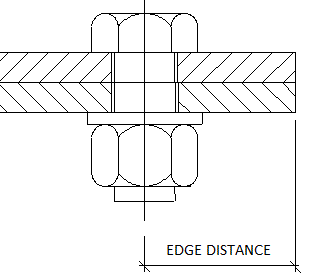
Edge distance is the distance from the centre of a bolt hole to the edge of the steel. Put a hole too close to an edge and the bolt does not fail — the steel does, tearing out through the edge in front of it. That is why every steel code carries a minimum, and why the number is measured from the hole centre rather than from the edge of the hole.
This page carries both charts: the metric one Australian detailers work to, and the imperial one used in the United States. They are not the same numbers and they are not derived the same way, so the second half of this page is about which is which.
Metric chart — AS 4100 (M12 to M36)
All distances in millimetres, from centreline of bolt to edge of steel.
| BOLT DIA | SHEARED OR HAND FLAME CUT | MACHINE CUT SAWN OR PLANED | ROLLED EDGE OF ROLLED SECTION | NORMAL PITCH |
|---|---|---|---|---|
| M12 | 25 | 20 | 15 | 45 |
| M16 | 30 | 25 | 20 | 60 |
| M20 | 35 | 30 | 25 | 70 |
| M24 | 45 | 40 | 30 | 90 |
| M30 | 55 | 45 | 40 | 100 |
| M36 | 65 | 55 | 45 | 100 |
Where the metric numbers come from
That chart has sat on this site for years without naming its source, which is worth fixing, because the source explains the three columns.
AS 4100 sets the minimum edge distance as a multiple of the bolt diameter, and the multiple depends on how the edge was made. A rough edge needs more steel behind the bolt than a clean one:
- 1.75 × bolt diameter — a sheared or hand flame cut edge.
- 1.50 × bolt diameter — a rolled plate edge, machine flame cut, sawn or planed.
- 1.25 × bolt diameter — the rolled edge of a rolled section.
Those three conditions are the three columns, in that order, and the column headings in the chart are the code’s own wording. Work the multipliers out for M20 and you get 35, 30 and 25 — the chart’s M20 row exactly.
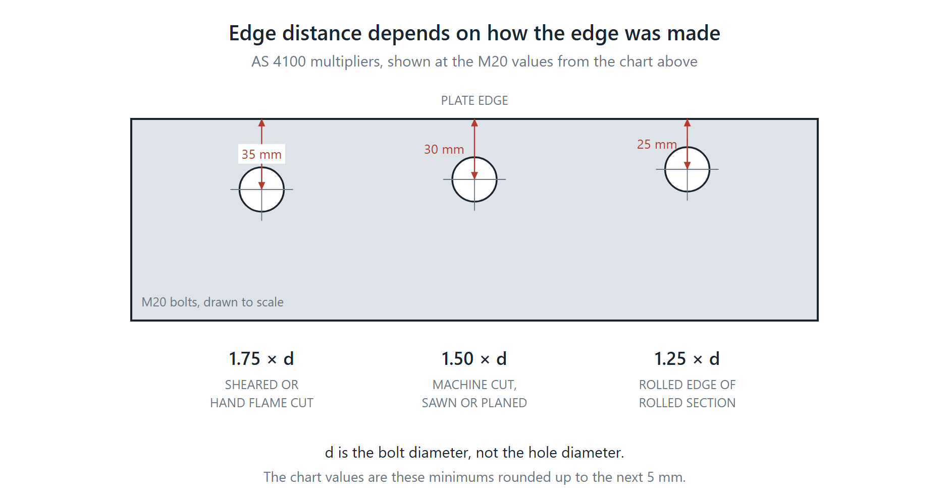
The other rows are the same calculation rounded up to the next 5 mm. M24 sheared is 1.75 × 24 = 42, tabulated as 45. M30 on a rolled edge is 1.25 × 30 = 37.5, tabulated as 40. Every one of the eighteen figures in those three columns is the code minimum rounded up to a number a detailer can actually dimension, which is why the chart is safe to work from and why it never quite matches a calculator.
Note that the multiplier is on the bolt diameter, not the hole diameter. An M20 in a 22 mm hole still uses 20 as the multiplicand.
The pitch column is not a code minimum
The last column is headed NORMAL PITCH, and normal is the right word for it. AS 4100’s minimum pitch — centre to centre between bolts — is 2.5 times the bolt diameter, which for M20 is 50 mm. The chart says 70.
That gap is deliberate and it is not an error. Code minimum pitch is what the steel can carry; normal pitch is what a person can actually build, with room for a socket to fit over the nut and for the bolt to be tensioned without fouling the one next to it. Detail to the normal pitch and you will rarely hear from the shop. Detail to 2.5d and you may.
Imperial chart — AISC (1/2 in. to 1-1/4 in.)
The American equivalent is Table J3.4 of ANSI/AISC 360, the Specification for Structural Steel Buildings. It is tabulated rather than given as a multiplier, and it applies to standard holes.
| BOLT DIA (in.) | MINIMUM EDGE DISTANCE (in.) | CONVERTED (mm) |
|---|---|---|
| 1/2 | 3/4 | 19 |
| 5/8 | 7/8 | 22 |
| 3/4 | 1 | 25 |
| 7/8 | 1-1/8 | 29 |
| 1 | 1-1/4 | 32 |
| 1-1/8 | 1-1/2 | 38 |
| 1-1/4 | 1-5/8 | 41 |
| Over 1-1/4 | 1-1/4 × d | 1.25 × d |
The millimetre column is a straight conversion of the inch column, provided so you can sanity-check an American drawing against a metric one. It is not AISC’s metric table. AISC publishes a separate metric companion, Table J3.4M, with its own rounded values for M16 to M36 — those are not conversions of the inch figures and you should not derive one series from the other.
As always with a chart on a website: confirm against the edition your project is designed to before you detail from it. The Specification is revised on a cycle, and a project designed to one edition is not automatically compliant with the next.
Why older American charts show two columns
If you have an edge distance chart pinned above your desk, or you find one on a forum, there is a good chance it has two columns of numbers rather than one — a larger set for sheared edges and a smaller set for rolled or thermally cut edges. That is not a mistake. It is the pre-2010 table.
AISC dropped the distinction in the 2010 Specification. The reasoning was that the bearing and tearout checks elsewhere in the code do not care how the edge was cut, and those checks had come to govern — so carrying a separate sheared-edge column in the edge distance table no longer bought anything. One column remains, and it is the smaller of the two former columns.
The practical consequences are worth spelling out, because they cut both ways:
- A chart printed before 2010 is not wrong, it is conservative. Detailing to it will not fail a check.
- But if you are reviewing someone else’s connection against an old chart, you will flag edge distances that the current code accepts.
- And a US drawing you are checking may legitimately show an edge distance smaller than an Australian eye expects, because AS 4100 still distinguishes the edge condition and AISC no longer does.
This is the single most common source of confusion when the same detailer works on drawings from both markets, which is why it gets a heading rather than a footnote.
Spacing, and the maximum
Edge distance is only half the geometry. Two more limits sit alongside it in AISC 360:
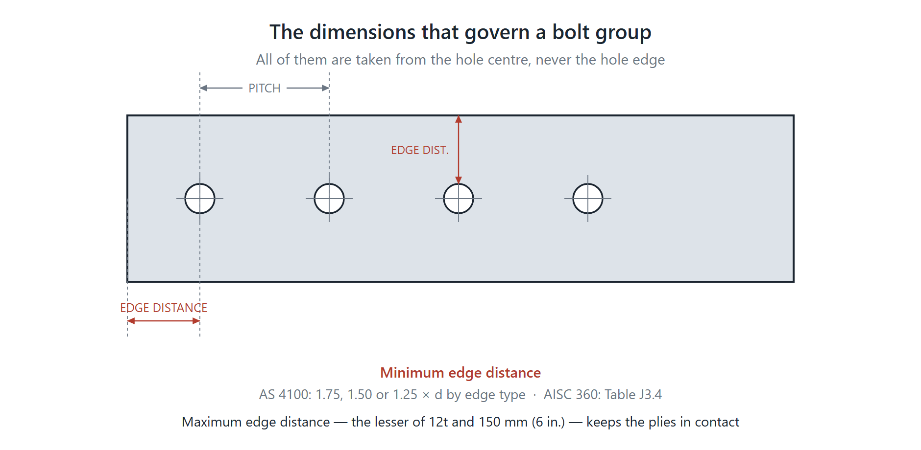
- Minimum spacing (J3.3) — centre to centre, not less than 2⅔ times the bolt diameter. Three diameters is preferred, and is what most shops would rather see.
- Maximum edge distance (J3.5) — the lesser of 12 times the thickness of the connected part, and 6 in. (150 mm).
The maximum surprises people. It exists so the plies stay in contact at the edge: a bolt too far from the edge leaves the plate free to lift and lets moisture in between the faying surfaces. It is a durability limit as much as a structural one, and it is the one most often missed on a wide gusset.
Which chart applies to your drawing
The code that applies is the one the project is designed to, not the one that matches your bolt units. That sounds obvious and is regularly got wrong on export work.
- Designed to AS 4100 — the metric chart, whatever units the model is in.
- Designed to AISC 360 — Table J3.4, including on a job detailed in millimetres.
- Neither named on the drawings — ask before you detail. Do not infer the code from the bolt series.
And whichever chart you use, these are minimums for the connection to work as designed. They are not a licence to move a hole inward until it just passes. If the engineer has dimensioned an edge distance on the design drawings, that dimension governs and the chart is only there to tell you whether it is plausible.
More steel detailing references
- Standard hole & slot sizes for bolts
- Calculating structural bolt lengths
- AWS weld symbols chart
- Printable steel detailing chart
References
- ANSI/AISC 360-22, Specification for Structural Steel Buildings — AISC’s own download page. Sections J3.3, J3.4 and J3.5 cover spacing, minimum edge distance and the maximum.
- ANSI webstore — ANSI/AISC 360-22
- Standards Australia — AS 4100:2020, Steel structures
- Standard hole and slot sizes for bolts — the hole the edge distance is measured from
- AWS weld symbols chart — the same two-market problem, on the welding side