
Last updated July 28, 2026
This one download gives you eleven commands for drawing fasteners: bolts in elevation, bolt heads and nuts in plan and elevation, washers, tapped holes, thread ends, cap screws and roll pins. Everything is drawn as geometry from a diameter you type, so there are no blocks to insert, rescale or lose.
The important thing, and the reason it deserves a place on an Australian site: it is metric. The routines size threads from a metric coarse pitch table, so you type 12 for an M12 and get sensible geometry. Most free fastener routines that circulate are imperial and quietly produce nonsense on a metric drawing. It is by Andrew Nielsen.
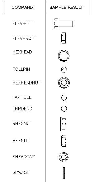
The eleven commands
- ELEVBOLT — a complete bolt in elevation with a threaded shank. Asks for head type (hex, socket or button), insertion point, direction, diameter and length.
- ELEVHBOLT — the same head geometry with no shank, for when the bolt disappears into the assembly.
- HEXHEAD — a hex bolt head in plan: hexagon with the two circles around it.
- HEXNUT — a hex nut in elevation, with a choice of plain or thin nut.
- RHEXNUT — a hex nut in elevation viewed across the corners rather than the flats.
- HEXHEADNUT — a hex nut in plan, with the thread circle shown.
- SHEADCAP — a socket head cap screw in plan, with the chamfer sized from a small lookup table.
- SPWASH — a washer in elevation, plain or spring.
- TAPHOLE — a tapped hole in plan: the thread circle with the conventional three-quarter arc.
- THRDEND — a thread end in plan, the same convention seen from the other side.
- ROLLPIN — a spring roll pin in plan, with the split shown.
Each one wraps its work in an undo group, so a single U removes the whole fastener rather than unpicking it line by line. Object snap is set to intersection while you pick the insertion point and to nearest while you pick a direction, then switched off to draw — a thoughtful touch that makes placing them on existing geometry quick.
Two things to know about the thread sizing
The routines work out a root diameter for the thread lines by subtracting one and a half times a pitch value from the nominal diameter. The pitch comes from a small lookup table, and that table is a simplification: every diameter from 8 up to 24 gets the same pitch value, where the real metric coarse series runs 1.25 at M8, 1.5 at M10, 1.75 at M12, 2.0 at M16 and 2.5 at M20. The thread lines it draws are therefore indicative, which is what a drawing symbol needs to be — just do not read the geometry as a thread specification.
There is also an inconsistency worth knowing if you draw a tapped hole and the bolt that goes into it. For diameters between 8 and 24, the bolt and nut commands use a pitch of 1.5, while TAPHOLE and THRDEND use 1.25. The root circle on the hole and the root lines on the bolt therefore will not match. It makes no difference on a plot at normal scale, but it will show if you zoom in or dimension off the geometry.
One side effect to be aware of: every command sets the current colour and linetype to BYLAYER before drawing and does not put your previous settings back. That is almost always what you want on a detail drawing, but if you were working with an explicit colour set, you will need to reset it afterwards.
How to load it
Unzip BOLTS.zip and load BOLTS.LSP with APPLOAD, or add it to the Startup Suite — with eleven commands in one file it earns its place there if you do mechanical detailing. There are no support files. Our AutoLISP guide covers loading.
Step-by-step usage
- Type the command for the view you want — say ELEVBOLT for a bolt in elevation.
- Answer the head type prompt where there is one: H for hex, S for socket, B for button.
- Pick the insertion point. Object snap is set to intersection to help you land on existing geometry.
- Pick the direction the bolt runs. Snap switches to nearest for this.
- Type the diameter — the nominal thread size, so 12 for an M12 — then the length where the command asks for one.
Draw one of each at a few sizes in a scratch drawing and keep it as a reference sheet. It is quicker than rediscovering which command gives which view.
Compatibility notes
The listing records it as working on AutoCAD 2006 and 2019, which is a good sign for a routine of this kind — it drives AutoCAD’s own PLINE, CIRCLE, POLYGON, ARC, LINE, TRIM, COPY and PEDIT commands rather than doing anything exotic.
It is plain AutoLISP with no dialog boxes and no Express Tools calls, so nothing in it requires the full product; LT users on LT 2024 or later, the release that brought AutoLISP to LT, should be able to run it. See what runs on AutoCAD LT.
Download
| Name: | BOLTS |
| Description: | Various routines for drawing bolts, nuts, washers and thread symbols. |
| Type: | AutoCAD AutoLISP Routine |
| Author: | Andrew NIELSEN |
| File Size: | 3 Kb |
| Cost: | Free |
| Worked on: | AutoCAD 2006, 2019 |
| Download File: | BOLTS.zip |
Related routines
- AWELD — welding symbols for the same detail drawings.
- Wisey’s Steel Shapes — Australian steel sections to bolt together.
- Best of LISP collection — general drafting utilities.