
Last updated August 2, 2026
By Steve
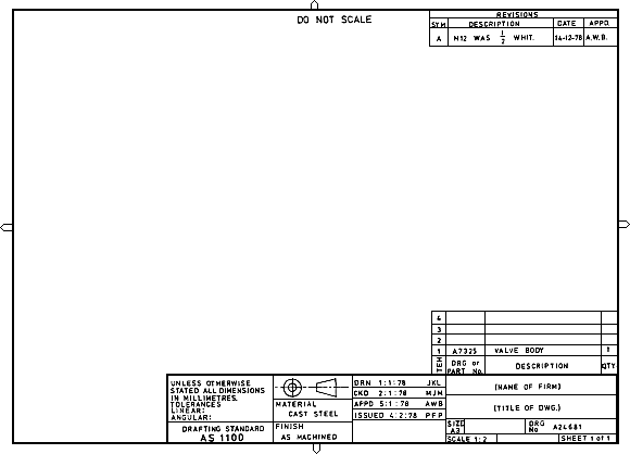
Standard layouts of drawing sheets are specified by the various standards organizations. This is the layout of a typical sheet, showing the drawing frame, the microfilm camera alignment marks, a typical title block, parts list and revision table.
Sheet Frames
It is standard practice for a drawing frame to be printed on each sheet, defining a margin around the outside of the drawing area. Drawing frames are standardized for each size of paper as per the following table.
Drawing Frames with No Filing Margin
| Paper Size | Border Left & Right (mm) | Border Top & Bottom (mm) | Frame Width (mm) | Frame Height (mm) |
|---|---|---|---|---|
| A0 | 28 | 20 | 1133 | 801 |
| A1 | 20 | 14 | 801 | 566 |
| A2 | 14 | 10 | 566 | 400 |
| A3 | 10 | 7 | 400 | 283 |
| A4 | 7 | 5 | 283 | 200 |
The frames follow the sheets: each frame is the previous one turned and halved, so the A1 frame width is the A0 frame height, and so on down. If you are checking a frame you have been given, that relationship is the quickest test — 1133, 801, 566, 400, 283, 200 is one series, each roughly 0.707 of the one before.
The borders grow with the sheet, and the left and right border is always larger than the top and bottom. That is not decoration — it is the allowance for the drawing to be trimmed and handled without losing anything inside the frame.
Title Block
The title block is normally placed in the bottom right of the drawing frame, and it should contain the following information:
- the name of the company or organization
- the title of the drawing
- the drawing number, which is generally a unique filing identifier
- the scale
- the angle of projection used, either first or third, generally shown symbolically
- the signature or initials of the draftsman, checker, approving officer, and issuing officer, with the respective dates
- other information as required
Bottom right is not arbitrary either. A drawing folded for filing ends up with its bottom right corner face up, so the title block is what you read without unfolding anything. Everything about the sheet layout assumes the drawing will be folded, filed and found again.
The projection symbol matters more than its size suggests. First angle and third angle put the views in different places, so a drawing read with the wrong assumption is a part made back to front.
What ISO 7200 actually requires
That list is long-standing drawing-office practice, and it is close to what AS 1100 asks for. The international standard for title block content, ISO 7200, takes a different approach: it names the fields, fixes how many characters each gets, and marks each one mandatory or optional. Nineteen fields in three groups, of which eight are mandatory.
Identifying fields — which document is this
| Field | Characters | Obligation | What it is for |
|---|---|---|---|
| Legal owner | unspecified | Mandatory | The firm or company that owns the document. May be a logo. |
| Identification number | 16 | Mandatory | The drawing number. Must be unique at least within the owner’s organisation. |
| Revision index | 2 | Optional | A, B, C … then AA, AB. Avoid I and O — they read as 1 and 0. |
| Date of issue | 10 | Mandatory | The date it was first officially released, and of every released version after. Matters legally: patent rights, traceability. |
| Segment / sheet number | 4 | Mandatory | Which sheet this is. |
| Number of segments / sheets | 4 | Optional | How many there are in total. |
| Language code | 4 per language | Optional | To ISO 639, for multilingual documents. |
Descriptive fields — what is on it
| Field | Characters | Obligation | What it is for |
|---|---|---|---|
| Title | 25 / 30 | Mandatory | What the document is. Chosen from established terms; abbreviations avoided. 30 characters supports two-byte languages. |
| Supplementary title | 2 × 25 / 30 | Optional | Further detail, e.g. “complete with brackets”. Written so the title still makes sense on its own. |
Administrative fields — who is answerable for it
| Field | Characters | Obligation | What it is for |
|---|---|---|---|
| Responsible department | 10 | Optional | The unit responsible for the content. |
| Technical reference | 20 | Optional | Who to ask about it. |
| Approval person | 20 | Mandatory | Who released it. |
| Creator | 20 | Mandatory | Who drew it. |
| Document type | 30 | Mandatory | Assembly drawing, part drawing, schedule. |
| Classification / key words | unspecified | Optional | For retrieval. |
| Document status | 20 | Optional | See drawing status below. |
| Page number | 4 | Optional | |
| Number of pages | 4 | Optional | |
| Paper size | 4 | Optional | A1, A3. |
Scale and the projection symbol are not in it
Read those three tables again and two familiar things are missing. Scale is not an ISO 7200 title block field. Neither is the projection symbol.
That is deliberate, and the standard says so: the number of data fields in the title block is kept to a minimum, while other fields are handled dynamically and shown outside the title block only when they are used — naming scale, projection symbol, general tolerance and surface texture requirements as the examples.
The logic is that a title block is a document management record. Scale is a property of a view, not of a document, and on a sheet carrying several scales the single title block entry is a lie anyway — which is why the convention of writing “scales as shown” exists in the first place. Australian and North American practice keeps both in the block regardless, and no client has ever objected. Know which you are following and why.
ISO 7200, AS 1100 and ANSI compared
| ISO 7200 | AS 1100 | ASME / ANSI | |
|---|---|---|---|
| Governs | Data fields in title blocks and document headers | Technical drawing, general principles | ASME Y14.100, engineering drawing practices |
| Approach | Names each field, fixes its length, marks it mandatory or optional | Describes what the block should contain | Defines lettered blocks; Y14.100 controls their content |
| Sheet sizes from | ISO 5457 and ISO 216 | AS 1100.101 | ASME Y14.1 |
| Title block position | Not fixed by the standard | Bottom right | Across the bottom |
| Revision block | Revision index field, 2 characters | Upper right, or left of the title block | Top right; revision practice in ASME Y14.35 |
| Scale in the block | No — handled outside it | Yes | Yes |
| Projection symbol | No — handled outside it | Yes, first angle | Yes, third angle |
| Zoning | Per ISO 5457 | Letters and numbers inside the frame | Letters and numbers, as on a map |
The ASME field list itself is defined in Y14.100, which is not published free. What is public is the structure: a bordered format with zone references, the revision block top right, the title block across the bottom, and lettered blocks whose contents Y14.100 controls. Most US companies simply reference Y14.100 on the drawing, which pulls in the rest of the Y14 series by reference.
Drawing status: for approval, for construction, for information
ISO 7200 provides a document status field, 20 characters, optional. What goes in it is not standardised, but the conventional terms carry real contractual weight and they are not interchangeable.
| Status | What it means | What you may do with it |
|---|---|---|
| For information | Issued so another party knows what is intended. Not a released design. | Read it. Coordinate against it. Do not build from it and do not order materials. |
| For approval / for review / for comment | Submitted for someone else to accept or mark up. The design is complete but not accepted. | Review and return comments. It will change. |
| For tender | Issued so contractors can price the work. | Price it. It is not necessarily the drawing you will build from. |
| For construction | Released to be built from. The one status that carries full liability. | Build it. Anything superseding it must be reissued and recorded. |
| As built / as constructed | Amended after the work to record what was actually built. | Use it for maintenance and future work, not for construction. |
| Preliminary / draft / not for construction | Work in progress. | Nothing. It exists so nobody mistakes it for one of the above. |
Two rules make the field work. Put the status where it cannot be missed — in the title block and, for anything that is not for construction, as a watermark across the sheet. And when the status changes, the drawing gets a new revision and a new date of issue, because the issue history is the only evidence of what was released when.
Material or Parts List
If the drawing contains a number of parts, or if it is an assembly drawing, a tabulated parts list is attached to the bottom right of the drawing frame, just above the title block. The parts list should give the following information:
- the part number
- the part name
- the quantity required
- material specifications
- the drawing number of each individual part
- other applicable information
The list builds upward from the title block, so the first part is at the bottom. That way adding a part does not move everything already on the sheet.
When the parts list is very large a separate drawing sheet may be used for the parts list alone.
Revision Table
A revision table is normally located in the upper right of the drawing frame, or at the bottom on the left side of the title block. All modifications to the drawing should be documented here.
A revision entry that says only “revised” has recorded nothing. It should say what changed and where, so that someone holding the previous issue can tell whether it still matters to them. That is the whole function of the table.
ISO 7200 keeps the revision index to two characters — A, B, C, then AA, AB, AC — and makes one specific recommendation worth adopting whatever standard you follow: avoid the letters I and O, because they are read as 1 and 0. A drawing at revision O and a drawing at revision 0 are not a distinction worth defending in a meeting.
Zoning
A drawing may be divided up into a grid using letters and numbers. When zoning is used it is located inside the drawing frame. Zoning allows easy references to various parts of the drawing by referencing a coordinate such as C/7.
It earns its keep on a large sheet and on revision entries — “revised at C/7” is a great deal more useful than “revised as shown”, especially when the drawing is being checked by someone who did not draw it.
Title block templates to download
Ready-made title block sheets, free, on our sister site. Metric A0 to A4, in both orientations:
- A0 Horizontal Title Block
- A0 Vertical Title Block
- A1 Horizontal Title Block
- A1 Vertical Title Block
- A2 Horizontal Title Block
- A2 Vertical Title Block
- A3 Horizontal Title Block
- A3 Vertical Title Block
- A4 Horizontal Title Block
- A4 Portrait Title Block
And the discipline-specific and North American sheets:
- A2 Sheet — Structural
- A3 Sheet — Architectural
- A0 Titleblock — Architectural
- A3 Borderless Sheet
- Consultants A3 Titleblock Sheet
- ANSI Standard Paper Size Titleblocks
- ANSI Architectural Titleblocks — Borderless
- ANSI Standard Paper Sizes — Grey Style
References
- ISO 7200:2004, Technical product documentation — Data fields in title blocks and document headers. Tables 1, 2 and 3 are the source of the field lists above; clause 4 is the source of scale and the projection symbol being handled outside the block. iso.org
- ISO 5457, Technical product documentation — Sizes and layout of drawing sheets, referenced normatively by ISO 7200. iso.org
- ASME Y14.100, Engineering Drawing Practices, which governs title block content in North American practice. asme.org
- ASME Y14.35, Revision of Engineering Drawings and Associated Documents. asme.org
- Standards Australia — AS 1100.101, Technical drawing: General principles
- Standard paper sizes — the ISO A series the frames above sit inside
- ANSI and Arch paper sizes — the North American equivalents, with a printable chart
- How to fold an A1 drawing — why the title block is bottom right
- Drawing scale chart — and why a multi-scale sheet says “scales as shown”
- Reduction ratios