
Last updated July 27, 2026
By Dave (Apr 2010)
Electrical symbols for circuit breakers, switches and contacts, to aid the design of single line diagrams and general electrical schematics. The chart below follows the Australian/New Zealand symbol standard — with one important caveat about that standard’s status, covered further down.
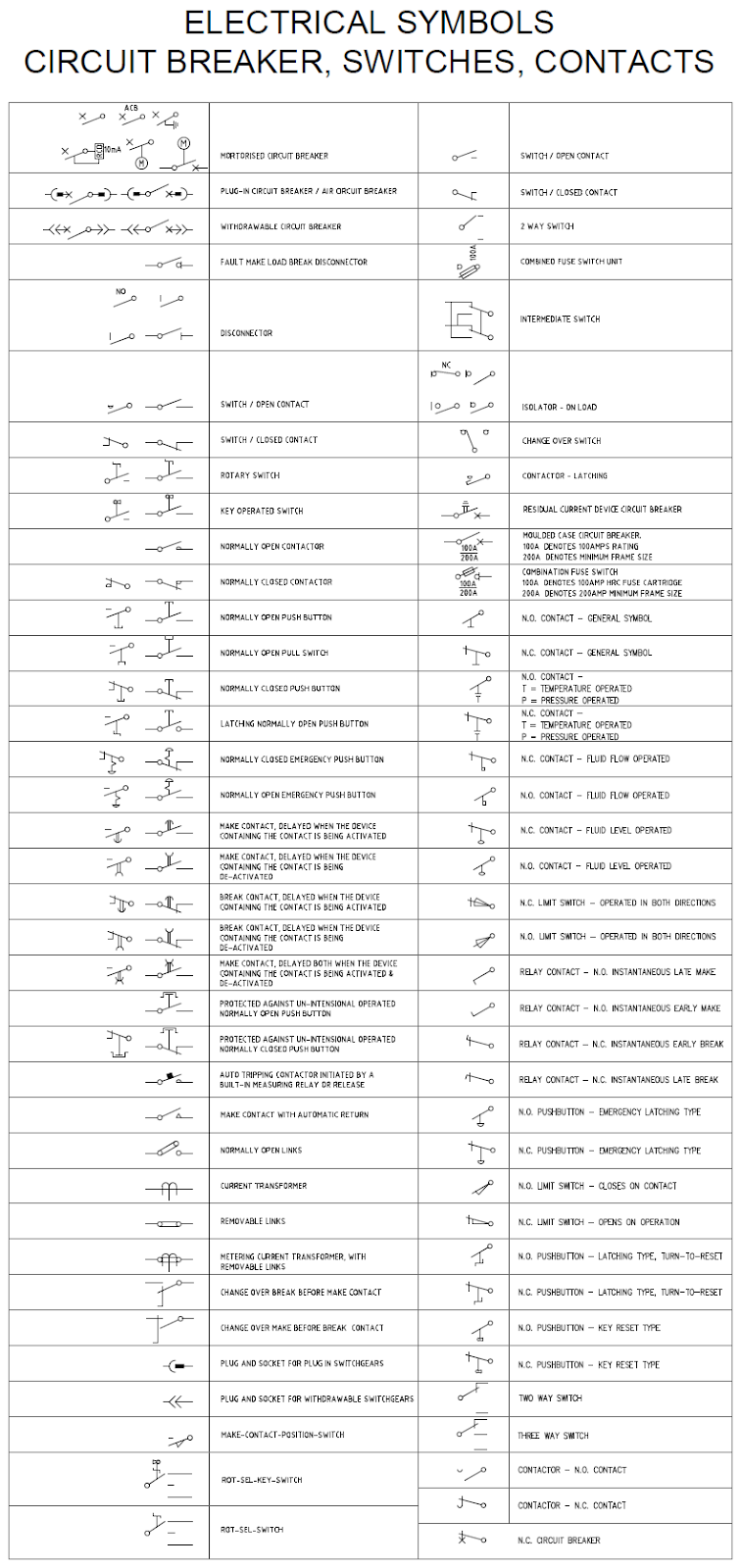
Download the CAD files for this chart — free, ready to insert.
Which standard these follow
Symbols of this kind sit in AS/NZS 1102.107:1997, Graphical symbols for electrotechnical documentation — Switchgear, controlgear and protective devices. Its scope covers switchgear, controlgear and protective devices, including starters, relays, proximity and touch-sensitive devices, igniters and flag indicators — which is exactly the territory of the chart above.
The series was published jointly by Standards Australia and Standards New Zealand, prepared by “the Joint Standards Australia/Standards New Zealand Committee TE/13, Symbols, Units and Quantities for Electrotechnology”.
And it has been withdrawn
This is the part worth knowing, and it is not something you will find stated on most symbol pages. Standards New Zealand — a joint publisher of the standard, so about as authoritative as it gets — lists AS/NZS 1102.107:1997 as Withdrawn, with the note:
This document has been withdrawn without replacement. You may wish to search for a more up to date equivalent.
The same is true across the series. The general-symbols part, AS/NZS 1102.102, is withdrawn. So is the passive components part, and the architectural installation plans part. There is no AS/NZS document that replaced them.
Standards New Zealand puts the general position bluntly on its listings: a withdrawn standard is unsupported practice, and while a standard can be withdrawn simply because no new edition superseded it, the practice it describes is considered outdated.
Practically, for a drafter, that means two things. The symbols themselves have not stopped working — drawings across Australia and New Zealand are full of them and everybody still reads them. But if a specification or a drawing register calls up AS/NZS 1102 by number, that reference is pointing at a withdrawn document, and it is worth raising rather than quietly copying forward.
What replaced it: IEC 60617
The living reference is the international one, IEC 60617, Graphical symbols for diagrams — and it is no longer a document at all. The IEC converted it into a database:
…has, as the first IEC standard, been converted into database form, accessible over the Internet.
The content of the database is the standard and designated IEC 60617 DB.
The IEC’s own definition of the arrangement is neat: “A Standard as database (SDB) is defined as a standard for which a valid form of publication is a database.” The initial content came from the 1996 paper edition and it has been maintained continuously since 2000.
Two details that matter if you are going to use it. It holds “more than 1500 graphical symbols for use in electrotechnical diagrams”, and — the useful bit for anyone drafting — the symbols are supplied in GIF, DWG and EPS formats. A DWG straight from the source beats redrawing one. It is a paid annual subscription, so it suits an office rather than an individual.
Finding the IEC equivalent of an AS/NZS part
There is a tidy rule for this, stated in the standard’s own preface:
The Part numbers in this series of Standards correspond to equivalent Parts in the IEC 617 series but with ‘100’ added to the IEC 617 Part number. For example, for the Standard IEC 617-2 refer to AS/NZS 1102.102. The symbol numbers within this Standard are the same as the IEC 617 numbers.
So subtract 100 and you have the IEC part. This page’s 1102.107 is IEC 617-7; the general symbols in 1102.102 are IEC 617-2. And because the symbol numbers themselves are unchanged, a symbol number off an old Australian chart will find the same symbol in the IEC database.
Why some Australian symbols look different anyway
The AS/NZS series was never a straight copy. Each part describes itself as “based on but not equivalent to, and reproduced from” its IEC counterpart, and the local differences were collected in an appendix:
Appendix ZA provides symbols for use in Australia and New Zealand which are additional to, or alternative to, the IEC 617 symbols. The symbols are identified with an ‘A’ in the third part of the symbol number.
That is the answer to a question that comes up regularly: an Australian chart and an IEC chart disagree, and neither is wrong. If a symbol number carries an A in its third group, it is a local variation and it will not be in the IEC set.
What a single line diagram actually is
Worth pinning down, because the term gets used loosely. The IEC’s own vocabulary defines it:
single-line diagram — a system diagram in which the polyphase links are represented by their equivalent single line
Set that against the neighbouring entry and the point becomes obvious:
three-phase system diagram — a diagram of a three-phase system in which all phase and neutral conductors are each represented by separate lines
One line standing in for all three phases, rather than three lines drawn out. That is the whole idea, and it is why a single line diagram of a substation fits on a sheet.
A schematic is a different job again. As electrical engineer John Livingston puts it, single line diagrams “show the overall conceptual layout of a circuit”, whereas a schematic “is a symbolic presentation of a system’s control elements that makes it easier to understand an electrical system’s functional logic”. Same symbols, different question being answered.
One thing these symbols are not: the Wiring Rules. AS/NZS 3000 governs how an installation is built and tested. AS/NZS 1102 governed how it is drawn. Different documents, different jobs, and only one of them is still current.
Related on this site
Electrical symbols — general covers the symbol elements and qualifying symbols, with its own chart and CAD download. There is also the full A–Z of drawing abbreviations.
References
- AS/NZS 1102.107:1997 — Graphical symbols for electrotechnical documentation: Switchgear, controlgear and protective devices — Standards New Zealand. Designation, title, scope, and the withdrawn-without-replacement status.
- AS/NZS 1102.102:1997 — Symbol elements, qualifying symbols and other symbols having general application — Standards New Zealand. Also withdrawn without replacement.
- AS/NZS 1102.106:1997 — publisher preview (front matter and preface) — Standards Australia / Standards New Zealand. Committee TE/13; the “based on but not equivalent to” wording; the +100 part-numbering rule; and Appendix ZA local variations.
- IEC 60617 DB — Graphical symbols for diagrams — IEC Webstore. Database format, more than 1500 symbols, GIF/DWG/EPS delivery, subscription terms.
- Standard as database — IEC Technical Committee 3. The SDB definition and the 2000 conversion from the 1996 paper edition.
- Graphical symbols for diagrams — IEC TC 3. “The content of the database is the standard and designated IEC 60617 DB.”
- single-line diagram, IEV 601-02-04 — IEC Electropedia (IEC 60050 International Electrotechnical Vocabulary).
- three-phase system diagram, IEV 601-02-03 — IEC Electropedia.
- The difference between single line and schematic diagrams — John Livingston, The Nuclear Electrical Engineer.