
Last updated July 27, 2026
A fly brace is a short brace — usually a small steel angle — running from the bottom flange of a portal frame rafter up to the roof purlin, restraining the rafter laterally. The same detail is used from a column’s inside flange across to a wall girt. A steel angle around 50x50x5mm is commonly used. Its job is to stop the flange that is in compression from buckling sideways.
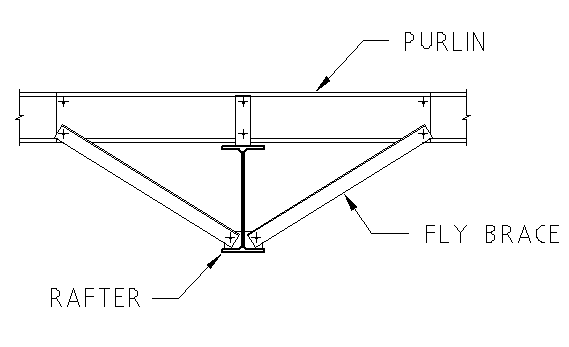
Need the detail rather than the explanation? Download the typical fly brace detail as a DWG — free, and ready to drop into your drawing.
What a fly brace actually does
A steel beam in bending has one flange in compression and one in tension. The compression flange behaves a bit like a column lying on its side: squeeze it hard enough and it wants to buckle sideways, dragging the section into a twist with it. Engineers call that lateral-torsional buckling, and it is what governs the capacity of most rafters.
Whichever flange is in compression is the one that matters. Steel Construction New Zealand’s portal frame guidance puts it in one line: “For a portal frame, the compression flange is the critical flange.”
Under ordinary gravity load — roof sheeting, services, a bit of wind pushing down — the top flange of the rafter is the one in compression, and it already has purlins bolted to it every metre or so. Nothing more is needed. As the same guidance notes, “Under gravity loads, the top flange is mostly in compression, except near the knees.”
Why the bottom flange, and why wind uplift governs
Then the wind gets under the building and tries to lift the roof off. The bending in the rafter reverses, and so does the flange that is in compression. Now the loaded flange is the bottom one — and the purlins are bolted to the other side.
Steel Construction New Zealand states it plainly:
Under uplift, most of the bottom flange of a portal frame rafter is in compression. In such cases, the rafter is attached to the purlins at the tension flange level, and the compression flange of the rafter is unrestrained. In order to achieve increased member capacity, it is customary to restrain the bottom flange of the rafter laterally by providing fly bracing using small angle section members joining the bottom flange to the purlins.
That is the whole idea. The fly brace reaches down from the purlin and grabs the flange that has nothing else holding it.
How much does it matter? Without any fly bracing under uplift, that guidance says the designer is left taking “the full portal span… as the effective length”, and adds that “the large effective length should equate to such a low capacity that some fly bracing will be necessary.” In other words: leave them out and the rafter is being asked to span the whole frame without lateral support, which it generally cannot do.
A note on that, because it matters if you are searching this term. There is a figure doing the rounds online claiming a missing fly brace cuts rafter capacity by some specific percentage. We went looking for the source and could not find one — it appears to be a number an AI assistant generated and other pages have since repeated. Do not quote it to your engineer.
Why the purlin on its own is not enough
This is the question that comes up on site: the purlin is already bolted to the rafter, so why not just make that connection stronger and skip the angle?
Because holding a beam sideways at the wrong flange barely helps. Citing testing by Dux and by Wong-Chung, the New Zealand guidance is blunt about it:
translational restraint alone acting at the level of the tension flange, such as that provided by purlins, is virtually ineffective. These studies show that if the lateral restraint is combined with some twist restraint, the buckling capacity is increased.
Virtually ineffective is strong language for an engineering document. The point is that the section fails by twisting, so a restraint has to resist the twist, not just push the top of the web sideways. Triangulating from the purlin down to the far flange does that; a bolt through the top does not.
There is an alternative — a stiffened moment connection between purlin and rafter — but Steel Construction New Zealand describes it as “inherently more flexible than a fly brace system which relies on a triangulated system to transfer the bottom flange restraint force… to the purlins.” The humble angle wins on stiffness.
Where they go along the frame
Placement is the engineer’s call, and it comes out of the frame analysis rather than a rule of thumb. What the published guidance will say is qualitative:
- Near each knee and near the ridge. Steel Construction New Zealand recommends a fly brace at each of these “to restrain the inside corners of the frame at kinks”.
- Through the haunch region. UK guidance points at the underside of the haunch where it meets the column flange — the point of highest compression in the inside flange anywhere in the frame.
- Wherever the analysis needs a restraint point to bring the effective length down to something the section can carry.
One piece of folklore worth correcting. You will read that fly braces go at the point of contraflexure. The New Zealand guidance says something close to the opposite when working out effective lengths: “The inflection point is considered to be unrestrained in determining the effective length.” A point of contraflexure is not a restraint. If you want a restraint there, you have to put one there.
You will also find spacing rules quoted around the traps — every second purlin, three metre centres, and so on. Shed manufacturers publish these for their own standard product ranges and they are reasonable within that context, but they are not a general rule and they are not in any standard we could open. Take the spacing off the engineer’s drawing.
The detail itself
In Australian practice a fly brace is typically a small equal angle — around 50x50x5 is common — bolted at each end, running from the purlin down to the rafter bottom flange. Whether it goes on one side of the web or both, the bolt size and count, and the exact angle are all detail decisions that follow the engineer’s design. Our typical fly brace DWG detail shows the arrangement we have drawn for years.
On the design side, one number is worth knowing about, with a caveat attached. New Zealand’s steel standard requires a restraint system to transfer “2.5 % of the critical flange force”, and Steel Construction New Zealand notes that no minimum stiffness value is given alongside it. That is NZS 3404, not AS 4100 — we are quoting it because it is published and readable, not because it applies on an Australian job. Check your own standard and your engineer’s numbers.
What it is called elsewhere
The term travels, but not intact. In the UK you will see “knee (or fly) bracing”, and British documents tend to talk about the inside flange of the column, haunch and rafter rather than the bottom flange — which is the better description once you follow the compression around a portal knee. North American metal building literature more often calls the member a flange brace.
If you are reading a drawing from another market, those are the words to look for.
The short version
- A fly brace restrains the rafter’s bottom flange by triangulating back to a purlin.
- It exists because wind uplift reverses the bending and puts the unrestrained flange into compression.
- A purlin alone will not do the job — restraint at the tension flange is described in the literature as virtually ineffective without twist restraint.
- Expect them near the knees, near the ridge, and through the haunch.
- Spacing, size and connection come from the engineer, not from a rule of thumb on the internet.
Related terms on this site: steel member designations, standard hole and slot sizes, bolt edge distances, and the full A–Z of drawing abbreviations.
References
- Portal Frame Design Tips Seminar Proceedings (Steel Advisor GEN7001) — Clark Hyland, Steel Construction New Zealand, 27 April 2010. Uplift and the unrestrained compression flange; the Dux and Wong-Chung findings on tension-flange restraint; fly braces near the knees and ridge; the inflection point treated as unrestrained. The document states it summarises material predominantly from two Australian Steel Institute publications, contextualised for New Zealand practice.
- Deep Rafter Stability (Steel Advisor MEM3601) — Alistair Fussell, Steel Construction New Zealand, 17 March 2009. The triangulated fly brace system versus the more flexible stiffened moment connection; the 2.5% critical flange force restraint requirement under NZS 3404.
- Designing portal frames — New Steel Construction (UK). “Knee (or fly) bracing”, and restraint of the inside flange around the eaves region.
- Restraints around portal frames — New Steel Construction (UK).
- Portal frames — SteelConstruction.info, the UK free encyclopaedia for steel construction.
- What is a fly brace in steel sheds — ShedBlog (Australia). Confirms the column-to-girt application alongside the rafter-to-purlin one.
- Typical fly brace detail (DWG) — blocks.draftsperson.net.