
Last updated July 28, 2026
Definition
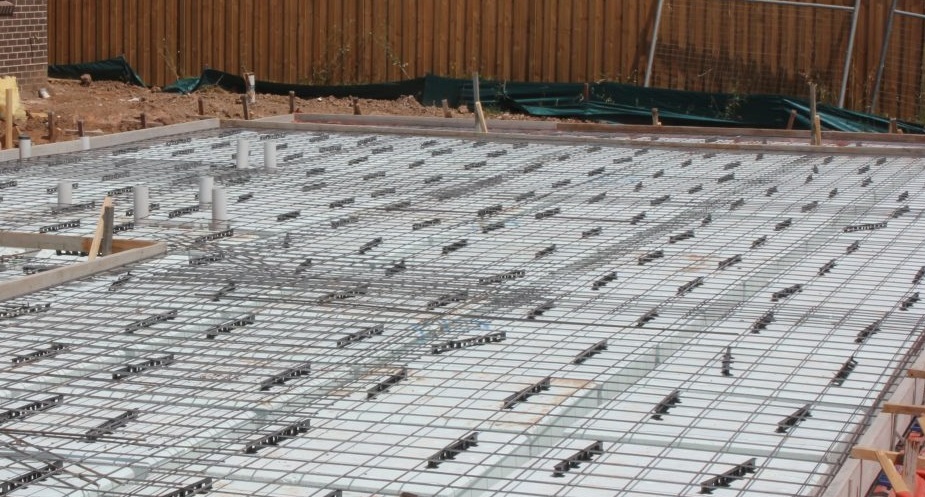
A two-way floor system consisting of a reinforced concrete slab poured with integral ribs in two directions beneath it. The system has a waffle-like pattern when viewed from below. The waffle “holes” are formed by square polystyrene pods.
The pods are formwork, not structure. They form the ribs and then they stay there because it is cheaper to leave them than remove them. Nothing is carried by the polystyrene, which is why the pods can be cut on plan to fit the floor layout — but never cut in thickness, because the thickness is what sets the rib depth.
Application
Domestic floor slabs on reasonably flat ground. Normally for class A and S sites with good site drainage.
The system sits on the ground rather than in it, which is the reason for the drainage conditions further down. A waffle pod slab is a raft: it works by being stiff enough to bridge over ground movement rather than by being founded below it.
Dimensions
Pods are 1090 mm square as standard, in four depths:
| Pod depth | Typically used for |
|---|---|
| 175 mm | “A” soil classification sites and special purposes |
| 225 mm | “S” and “M” classification sites |
| 300 mm | “M” and low “H” classification sites |
| 375 mm | “H” classification sites |
Refer to AS 2870 for soil classifications. As a rough guide, A is not reactive and H is more reactive — the more the ground moves with moisture, the deeper the slab has to be to ride over it.
The rest of the geometry:
- 110 mm gap between the pods, which forms the internal ribs.
- 300 mm wide edge beam, with a 150 mm wide rebate for the first two courses of brick veneer.
- Minimum edge beam depth 150 mm.
- Internal and edge beams and ribs must be continuous through the slab and at re-entrant corners.
- 85 mm thick slab, continuous over the top of the pods.
- Slab at least 150 mm above ground; 100 mm in well-drained sand; 50 mm next to paving that slopes away from the building.
The 1090 + 110 gives a 1200 mm grid, which is the number worth remembering when you set out. Ribs land on a 1200 module in both directions and the pods fill between them.
Reinforcement
Refer to AS 2870 for reinforcement details. As a typical guide:
- SL72 mesh, top, in the slab.
- N12 continuous in the bottom of the ribs.
- 3–N12 x 2000 long trimmers, top, at re-entrant corners.
- 3–L8TM200 trench mesh in the bottom of the edge beam.
Note where the steel sits: mesh in the top of the slab, bars in the bottom of the ribs. That is the shape of the bending in a raft — hogging over the stiff bits, sagging in the ribs — and it is the thing most often drawn upside down by someone working from memory.
Accessories
- Four-way corner spacer (4W-110) — HDPE plastic, seats on the corner of the pods to support the reinforcement in the bottom of the ribs.
- Two-way spacer (2W-110) — seats between pods, same job along a rib rather than at a junction.
Other notes
- Avoid water ponding against the footing. Ground to slope away, or provide drainage.
- Minimum concrete grade N20 (f’c 20 MPa).
- For polished slabs, minimum N32 (f’c 32 MPa) and SL82 mesh top. Stronger concrete is more prone to shrinkage, hence the heavier reinforcement.
That last point is worth reading twice, because it is counter-intuitive: specifying stronger concrete for a polished finish makes the slab more likely to crack, not less, and the extra mesh is there to control it. If a client asks for a polished slab late in the design, the reinforcement schedule changes.
What to show on the drawing
- Pod layout in plan on the 1200 grid, with cut pods shown where they meet the edge beam or an internal beam.
- Edge beam and internal beam setout, with the brick rebate dimensioned.
- A typical section through the edge beam and a typical section through the ribs and pods.
- Trimmer bars at every re-entrant corner — and check the plan for corners you did not notice.
- Slab level relative to finished ground level, so the height above ground can be read.
- Service penetrations. A pod is easy to cut around; a rib is not.
References
- Standards Australia — AS 2870, Residential slabs and footings — the governing standard for site classification and reinforcement
- Standards Australia — AS 3600, Concrete structures
- Structural slab joints
- FFL on a drawing
- Acronyms and abbreviations in engineering