Last updated July 27, 2026
This page is part of our complete AWS weld symbols guide, which covers every weld type and supplementary symbol with the current AWS A2.4:2020 changes.
This information applies to the American Steel Industry
Also check out the American Welding Society – Weld Symbols Chart
When welds are specified on engineering and fabrication drawings, a cryptic set of symbols is used as a sort of shorthand for describing the type of weld, its size, and other processing and finishing information. The purpose of this page is to introduce you to the common symbols and their meaning. The complete set of symbols is given in a standard published by the American National Standards Institute and the American Welding Society.
The structure of the welding symbol

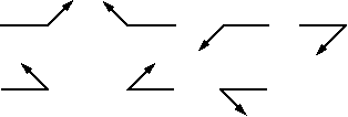
The horizontal line–called the reference line–is the anchor to which all the other welding symbols are tied. The instructions for making the weld are strung along the reference line. An arrow connects the reference line to the joint that is to be welded. In the example above, the arrow is shown growing out of the right end of the reference line and heading down and to the right, but many other combinations are allowed.
Quite often, there are two sides to the joint to which the arrow points, and therefore two potential places for a weld. For example, when two steel plates are joined together into a T shape, welding may be done on either side of the stem of the T.
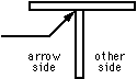
The weld symbol distinguishes between the two sides of a joint by using the arrow and the spaces above and below the reference line. The side of the joint to which the arrow points is known (rather prosaically) as the arrow side, and its weld is made according to the instructions given below the reference line. The other side of the joint is known (even more prosaically) as the other side, and its weld is made according to the instructions given above the reference line. The below=arrow and above=other rules apply regardless of the arrow’s direction. The flag growing out of the junction of the reference line and the arrow is present if the weld is to be made in the field during erection of the structure. A weld symbol without a flag indicates that the weld is to be made in the shop. In older drawings, a field weld may be denoted by a filled black circle at the junction between the arrow and the reference line.
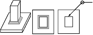
The open circle at the arrow/reference line junction is present if the weld is to go all around the joint, as in the example below.
The tail of the weld symbol is the place for supplementary information on the weld. It may contain a reference to the welding process, the electrode, a detail drawing, any information that aids in the making of the weld that does not have its own special place on the symbol. Each type of weld has its own basic symbol, which is typically placed near the center of the reference line (and above or below it, depending on which side of the joint it’s on). The symbol is a small drawing that can usually be interpreted as a simplified cross-section of the weld. In the descriptions below, the symbol is shown in both its arrow-side and other-side positions.
Types of welds and their symbols
Fillet welds

The fillet weld (pronounced “FILL-it,” not “fil-LAY”) is used to make lap joints, corner joints, and T joints. As its symbol suggests, the fillet weld is roughly triangular in cross-section, although its shape is not always a right triangle or an isosceles triangle. Weld metal is deposited in a corner formed by the fit-up of the two members and penetrates and fuses with the base metal to form the joint. (Note: for the sake of graphical clarity, the drawings below do not show the penetration of the weld metal. Recognize, however, that the degree of penetration is important in determining the quality of the weld.)
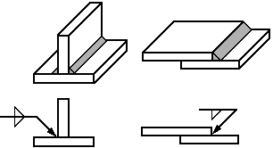
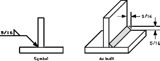
The perpendicular leg of the triangle is always drawn on the left side of the symbol, regardless of the orientation of the weld itself. The leg size is written to the left of the weld symbol. If the two legs of the weld are to be the same size, only one dimension is given; if the weld is to have unequal legs (much less common than the equal-legged weld), both dimensions are given and there is an indication on the drawing as to which leg is longer.
The length of the weld is given to the right of the symbol.
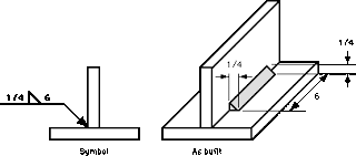
If no length is given, then the weld is to be placed between specified dimension lines (if given) or between those points where an abrupt change in the weld direction would occur (like at the end of the plates in the example above).For intermittent welds, the length of each portion of the weld and the spacing of the welds are separated by a dash (length first, spacing second) and placed to the right of the fillet weld symbol.

Groove welds
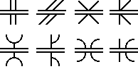
The groove weld is commonly used to make edge-to-edge joints, although it is also often used in corner joints, T joints, and joints between curved and flat pieces. As suggested by the variety of groove weld symbols, there are many ways to make a groove weld, the differences depending primarily on the geometry of the parts to be joined and the preparation of their edges. Weld metal is deposited within the groove and penetrates and fuses with the base metal to form the joint. (Note: for the sake of graphical clarity, the drawings below generally do not show the penetration of the weld metal. Recognize, however, that the degree of penetration is important in determining the quality of the weld.)
The various types of groove weld are:
Square groove weld

The square groove weld, in which the “groove” is created by either a tight fit or a slight separation of the edges. The amount of separation, if any, is given on the weld symbol.

V-groove weld

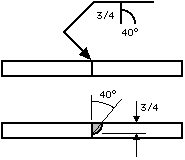
The V-groove weld, in which the edges of both pieces are chamfered, either singly or doubly, to create the groove. The angle of the V is given on the weld symbol, as is the separation at the root (if any)
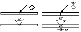
If the depth of the V is not the full thickness–or half the thickness in the case of a double V–the depth is given to the left of the weld symbol.

If the penetration of the weld is to be greater than the depth of the groove, the depth of the effective throat is given in parentheses after the depth of the V.
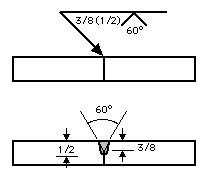
Bevel groove weld

The bevel groove weld, in which the edge of one of the pieces is chamfered and the other is left square. The bevel symbol’s perpendicular line is always drawn on the left side, regardless of the orientation of the weld itself. The arrow points toward the piece that is to be chamfered. This extra significance is emphasized by a break in the arrow line. (The break is not necessary if the designer has no preference as to which piece gets the edge treatment or if the piece to receive the treatment should be obvious to a qualified welder.) Angle and depth of edge treatment, effective throat, and separation at the root are described using the methods discussed in the V-groove section.
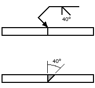
U-groove weld

The U-groove weld, in which the edges of both pieces are given a concave treatment. Depth of edge treatment, effective throat, and separation at the root are described using the methods discussed in the V-groove section
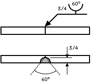
J-groove weld

The J-groove weld, in which the edge of one of the pieces is given a concave treatment and the other is left square. It is to the U-groove weld what the bevel groove weld is to the V-groove weld. As with the bevel, the perpendicular line is always drawn on the left side and the arrow (with a break, if necessary) points to the piece that receives the edge treatment. Depth of edge treatment, effective throat, and separation at the root are described using the methods discussed in the V-groove section.
Flare-V groove weld

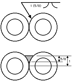
The flare-V groove weld, commonly used to join two round or curved parts. The intended depth of the weld itself are given to the left of the symbol, with the weld depth shown in parentheses.
Flare bevel groove weld

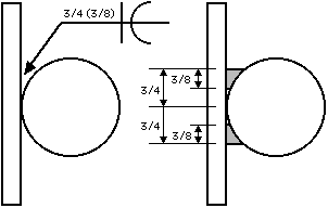
The flare bevel groove weld, commonly used to join a round or curved piece to a flat piece. As with the flare-V, the depth of the groove formed by the two curved surfaces and the intended depth of the weld itself are given to the left of the symbol, with the weld depth shown in parentheses. The symbol’s perpendicular line is always drawn on the left side, regardless of the orientation of the weld itself.
Supplementary symbols used with groove welds


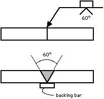
Common supplementary symbols used with groove welds are the melt-thru and backing bar symbols. Both symbols indicate that complete joint penetration is to be made with a single-sided groove weld. In the case of melt-thru, the root is to be reinforced with weld metal on the back side of the joint. The height of the reinforcement, if critical, is indicated to the left of the melt-thru symbol, which is placed across the reference line from the basic weld symbol.
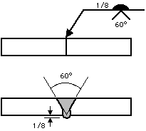
When a backing bar is used to achieve complete joint penetration, its symbol is placed across the reference line from the basic weld symbol. If the bar is to be removed after the weld is complete, an “R” is placed within the backing bar symbol. The backing bar symbol has the same shape as the plug or slot weld symbol, but context should always make the symbol’s intention clear.
Plug and slot welds

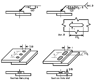
Plug welds and slot welds are used join overlapping members, one of which has holes (round for plug welds, elongated for slot welds) in it. Weld metal is deposited in the holes and penetrates and fuses with the base metal of the two members to form the joint. (Note: for the sake of graphical clarity, the drawings below do not show the penetration of the weld metal. Recognize, however, that the degree of penetration is important in determining the quality of the weld.)For plug welds, the diameter of each plug is given to the left of the symbol and the plug-to-plug spacing (pitch) is given to the right. For slot welds, the width of each slot is given to the left of the symbol, the length and pitch (separated by a dash) are given to the right of the symbol, and a detail drawing is referenced in the tail. The number of plugs or slots is given in parentheses above or below the weld symbol. The arrow-side and other-side designations indicate which piece contains the hole(s). If the hole is not to be completely filled with weld metal, the depth to which it is to be filled is given within the weld symbol.