
Tap sizeDiameter (in)Diameter (mm)Thread count (TPI)Thread pitch (mm)Tap drill size#0000-1600.02100.53341600.1591/64 in#000-1200.03400.86361200.212#71M1x0.20.03941.0000~1270.2000.8 mmM1x0.250.03941.0000~1020.2500.75 mmM1.1x0.250.04331.1000~1020.2500.85 mmM1.1x0.20.04331.1000~1270.2000.9 mm#00-900.04701.1938900.282#65M1.2x0.20.04721.2000~1270.2001 … [Read more...] about ISO Metric Tap and Die Chart: Drill Sizes and Pitch
ISO 13567 – CAD layer standard
ISO 13567 is an international Computer-aided design (CAD) layer standard.Standard partsThe standard is divided in three parts:ISO 13567-1:1998Technical product documentation -- Organization and naming of layers for CAD -- Part 1: Overview and principlesISO 13567-2:1998Technical product documentation -- Organization and naming of layers for CAD -- Part 2: Concepts, format … [Read more...] about ISO 13567 – CAD layer standard
How to Fold an A1 Drawing to A4 – Step-by-Step + Diagram
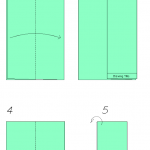
An A1 drawing folds down to an A4 sheet in four folds — three concertina folds across the length, one across the height — finishing with the title block facing up so the drawing can be identified without unfolding it. The diagram below shows the sequence, and the written steps follow underneath. The folding sequence, A1 down to A4. Why the sizes work out An … [Read more...] about How to Fold an A1 Drawing to A4 – Step-by-Step + Diagram
Grid Systems on Drawings: Setout, Naming and Direction

A grid reference system consists of one set of gridlines in one direction with a second set of gridlines in another direction. Any grid system shall be consistent throughout a project. Grid systems are generally right angles to each other, but grid lines do not necessarily have to be at right angles to each other. The project grid may be adopted with a completely arbitrary … [Read more...] about Grid Systems on Drawings: Setout, Naming and Direction
General Symbols and Identification Methods
Commonly used symbols on drawings and what they mean. … [Read more...] about General Symbols and Identification Methods
Electrical Symbols – General (Free CAD Download)

By Dave (Apr 2010) General electrical symbols — the symbol elements and qualifying symbols that the rest of the set is built from — to aid the design of single line diagrams and general electrical schematics. The chart follows the Australian/New Zealand symbol standard, with a caveat about that standard’s status below. Download the CAD files for this … [Read more...] about Electrical Symbols – General (Free CAD Download)