
Last updated July 27, 2026
By DGM
A welding symbol is a sentence. Once you know where the words go, you can read any of them — and there are only about six places anything can sit.
This page takes it one piece at a time and then reads two real symbols end to end. If you want the complete reference instead, the AWS weld symbols chart and guide covers every weld type, the supplementary symbols and how the dimensions are placed.
Welding symbols used in Australia are covered by AS 1101.3-2005 (R2018), Graphical symbols for general engineering, Part 3: Welding and non-destructive examination — see weld symbols on Australian drawings for how the Australian convention compares with the American and ISO systems.
The parts of a welding symbol
The standard lists eight elements. In practice you will meet four of them constantly and the rest occasionally:
- The reference line — the horizontal line everything hangs off. This is the spine of the sentence.
- The arrow — points at the joint being welded.
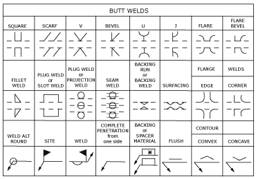
- The weld symbol — the little shape saying what kind of weld: a triangle for a fillet, a square for a square butt, and so on.
- Dimensions and other data — how big, how long, how often.
- Supplementary symbols — weld all round, weld on site.
- Finish symbols, the tail, and specification or process references that go in it.
Worth getting the vocabulary straight early, because the standards are precise about it and most people are not: the weld symbol is the shape that says what kind of weld. The welding symbol is the whole assembly — line, arrow, shape, numbers and all. Both AS 1101.3 and AWS A2.4 make the same distinction.
The one rule that matters most
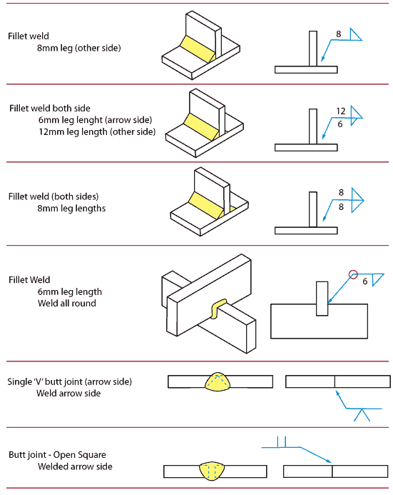
If you learn nothing else, learn this. Which side of the reference line the symbol sits on tells the welder which side of the joint to weld:
Information relating to the ‘arrow side’ of the joint is placed below the reference line and information relating to the ‘other side’ of the joint is placed above the reference line.
Below the line = the side the arrow is touching. Above the line = the far side.
That is it. It holds regardless of which end of the reference line the arrow comes off, and regardless of which way the arrow points. A symbol on both sides of the line means weld both sides.
It is worth being deliberate about this one, because it is the single most consequential thing on the drawing and it is the thing that changes when a drawing arrives from Europe. Under the ISO system there is a second, dashed reference line doing this job instead, and the above-or-below habit will mislead you. That is covered on the Australian weld symbols page.
Where the numbers go
Two positions, and they do not move:
- Size goes to the left of the weld symbol. For a fillet weld on an Australian drawing that number is the leg length.
- Length goes to the right. If the weld is intermittent, the pitch follows the length after a hyphen — so
50-150means 50 mm long at 150 mm centres.
Anything about how the weld is to be made — the process, a specification, a procedure number — belongs in the tail. The standard puts it plainly: specification and process references should be shown in the tail of the welding symbol.
Weld finishes, or contour
With butt welds the symbol also tells you the final shape of the finished weld:
- It may be ground off flush.
- It may be left in its original state — convex.
- Concave welds are rarely used.
The practical point is that a finish call-up is an instruction to do more work after welding. Grinding a weld flush costs time, so it appears when there is a reason — a surface that has to be flat, a fit-up that will not clear otherwise.
Reading two real symbols
Now put it together. Compare these two symbols — note what is different, and what each one means.
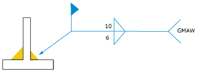
Read it in four pieces:
- 10 mm fillet weld, other side of the arrow — a triangle above the reference line with 10 to its left.
- 6 mm fillet weld, arrow side — the same again below the line, at 6.
- Weld on site — not in the shop; the fabricator leaves this one for the erector.
- Use the gas metal arc welding process — called up in the tail.
So: fillet welds both sides of the joint at different sizes, done on site, by GMAW. Two different leg lengths on one joint is common enough — the loads are rarely symmetrical.

- 6 mm fillet weld on both sides — same size above and below the line this time.
- Weld all round — the weld continues around the whole joint, not just the length the arrow touches.
- Weld on site.
- Use the gas metal arc welding process.
Weld-all-round is worth pausing on, because it is the cheapest thing on a drawing to write and one of the more expensive to build. On a hollow section going through a plate it is exactly right. Added out of habit to a joint that does not need it, it buys nothing but welding time and distortion.
Where to go next
That is the whole grammar. Everything else is vocabulary — more weld types, more supplementary symbols — and it all hangs off the same reference line in the same positions.
- The complete AWS weld symbols chart and guide — every weld type and supplementary symbol, with a free printable chart.
- Weld symbols on Australian drawings — AS 1101.3, and what changes when the drawing comes from America or Europe.
- American weld symbols illustrated — every symbol with a diagram.
References
- AS 1101.3-2005 (R2018) — Graphical symbols for general engineering, Part 3: Welding and non-destructive examination — Standards Australia.
- AS 1101.3-2005 (R2018) — publisher preview (front matter and preface) — the eight elements of a welding symbol (Clause 2.1.1) and specification references in the tail (Clause 2.1.5). Size-left and length-right placement and the intermittent weld pitch rule are in the second preview extract. See the Australian weld symbols page for the full sourced detail.
- Welding symbols — The National Board of Boiler and Pressure Vessel Inspectors. The arrow-side and other-side placement rule.
- AWS A2.4:2020 — Standard Symbols for Welding, Brazing, and Nondestructive Examination, preview — American Welding Society. Clause 4.1, the distinction between weld symbol and welding symbol.
- Engineering Drawing Handbook — Standards Australia and the Institution of Engineers.